Chrysler PT Cruiser. Manual - part 790
(5) Position
transaxle
with
bellhousing
facing
down on workbench with C-clamps. Position dial
indicator.
NOTE: Position of dial indicator in (Fig. 64) is for
illustrative purposes only. The dial indicator should
be parallel to T-Handle to obtain the most accurate
reading.
(6) Apply a medium load to differential with Tool
C-4995 and a T-handle, in the downward direction.
Roll differential assembly back and forth a number of
times. This will settle the bearings. Zero the dial
indicator. To obtain end play readings, apply a
medium load in an upward direction while rolling
differential assembly back and forth (Fig. 64). Record
end play.
(7) The shim required for proper bearing preload is
the total of end play, plus (constant) preload of
0.18mm (0.007 in.). Never combine shims to obtain
the required preload.
(8) Remove case bolts. Remove clutch bellhousing
differential bearing cup. Install shim(s) selected in
Step 7. Then press the bearing cup into clutch bell-
housing.
(9) Install clutch bellhousing. Install and torque
case bolts to 26 N·m (19 ft. lbs.).
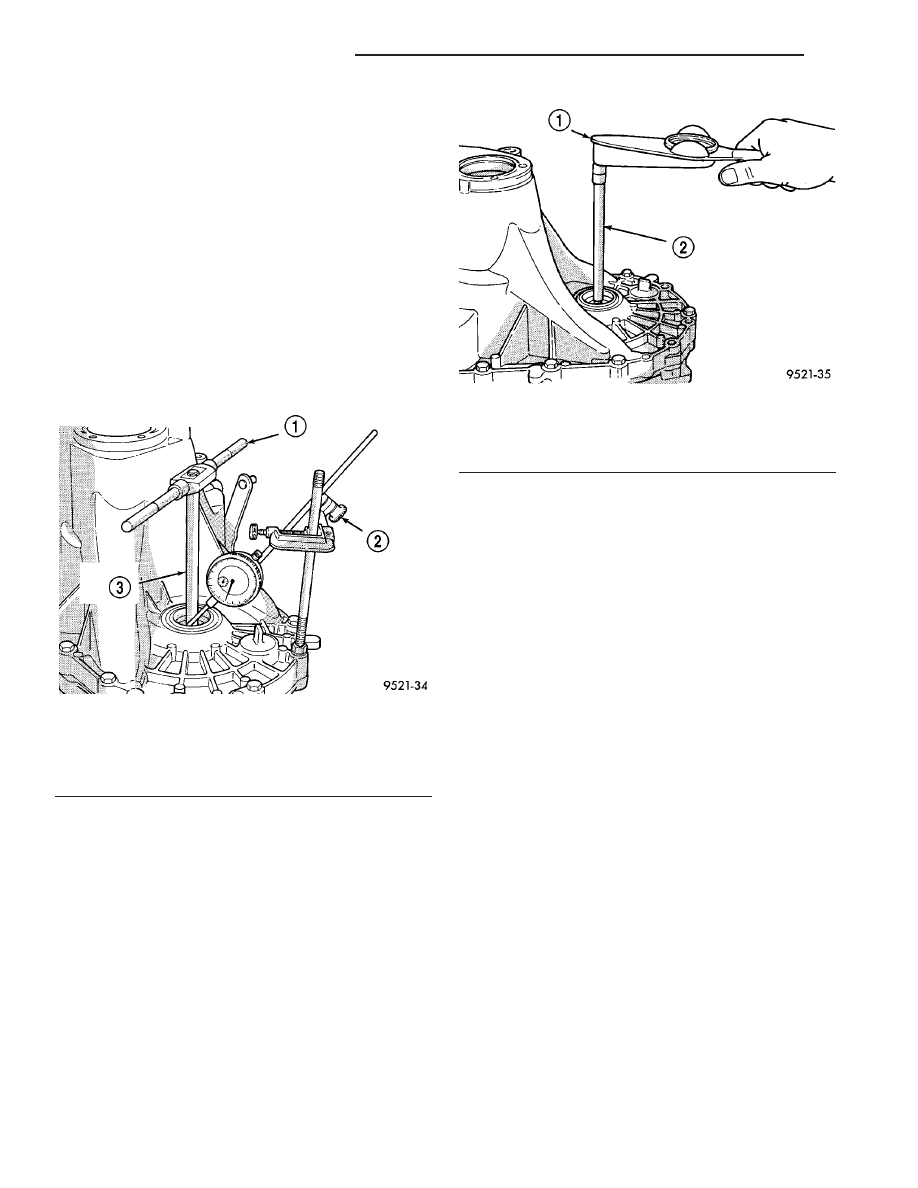
(10) Using Special Tool C-4995 and an inch-pound
torque wrench, check turning torque of the differen-
tial assembly (Fig. 65). The turning torque should
be 6 to 12 in. lbs. If the turning torque is too
high, install a 0.05mm (0.002 inch) thinner shim.
If the turning torque is too low, install a
0.05mm (0.002 inch) thicker shim.
(11) Recheck turning torque. Repeat Step 10 until
the proper turning torque is obtained.
Once proper turning torque has been established,
place gear case on the end plate. Draw a bead of
Mopar
t Gasket Maker, Loctitet 518, or equivalent,
on the flat surface of the case mating flange. Install
clutch bellhousing onto gear case. Install and tighten
case bolts to 29 N·m (21 ft. lbs.).
INSTALLATION
(1) Install clutch module (if equipped) onto input
shaft. Install transaxle into position.
(2) Install transaxle-to-engine mounting bolts (Fig.
20) and tighten to 108 N·m (80 ft. lbs.) torque.
(3) Raise engine and transaxle with screw jack
until upper mount bracket aligns with upper mount.
Install mount bolts and tighten to 68 N·m (50 ft. lbs.)
torque (Fig. 19).
(4) Remove screwjack.
(5) Install four (4) modular clutch-to-driveplate
bolts (Fig. 66). Align drive plate and modular clutch
alignment marks placed upon disassembly. Start
with tight-tolerance (slotted) hole, install and torque
bolts to 88 N·m (65 ft. lbs.) torque.
(6) Install starter motor and tighten bolts to 54
N·m (40 ft. lbs.) torque. Make sure to fasten ground
cable to upper starter bolt as shown in (Fig. 18).
(7) Connect starter electrical harness and tighten
positive cable nut to 10 N·m (90 in. lbs.) torque.
(8) Install bellhousing dust cover (Fig. 16).
(9) Install left engine-to-transaxle bending brace
and structural collar (Fig. 15). Refer to ENGINE for
proper tightening procedure.
(10) Install power steering hose to structural col-
lar.
Fig. 64 Checking Differential Bearing End Play To
Determine Shim Thickness
1 - T-HANDLE
2 - DIAL INDICATOR SET
3 - SPECIAL TOOL C-4995
Fig. 65 Checking Differential Bearing Turning
Torque
1 - INCH-POUND TORQUE WRENCH
2 - SPECIAL TOOL C-4995
21 - 114
T350 MANUAL TRANSAXLE
PT
T350 MANUAL TRANSAXLE (Continued)