Chrysler PT Cruiser. Manual - part 745


  Index      Chrysler     Chrysler PT Cruiser - service repair manual 2005 year


Search            


Content   ..  743  744  745  746   ..


Chrysler PT Cruiser. Manual - part 745


(6) Tighten throttle cable bracket bolts to 11.8

±2.25 N·m (105 ±20 in. lbs.) torque.

(7) Install EVAP purge hose to throttle body nip-

ple.

(8) Install cable housing(s) retainer tabs into

bracket (Fig. 52).

(9) Install throttle body cables by rotating the

throttle cam forward to the wide open position (Fig.
51).

(10) Install throttle control shield.
(11) Install the negative battery cable.
(12) Install the air cleaner lid, connect the inlet air

temperature sensor and makeup air hose.

INSTALLATION - 1.6L

NOTE: The electrical connector must be pointed
toward the front of vehicle and purge nipple must
be in the up position for proper orientation of the
throttle body.

(1) Make sure that the mating surfaces for the

throttle body and intake manifold are clean.

(2) When installing the throttle body making sure

that the gasket is installed in the throttle body (Fig.
63) and (Fig. 64). Align the tabs on the manifold to
the pin alignment slots in throttle body, make sure
that the purge nipple is pointed up and electrical
connector are pointed toward the front of vehicle.

(3) Install throttle, install so that the purge nipple

is pointing up. The locating tabs (Fig. 65) on the
upper intake will locate the throttle body in the
proper orientation.

(4) Install the 4 bolts (Fig. 56) and tighten the

bolts in a cross pattern to 11.8 N·m (105 in. lbs.).

(5) Install the purge hose.

(6) Connect the electrical connector (Fig. 55).
(7) Connect the negative battery cable.
(8) Install the air cleaner cover.

INSTALLATION - 2.4L TURBO

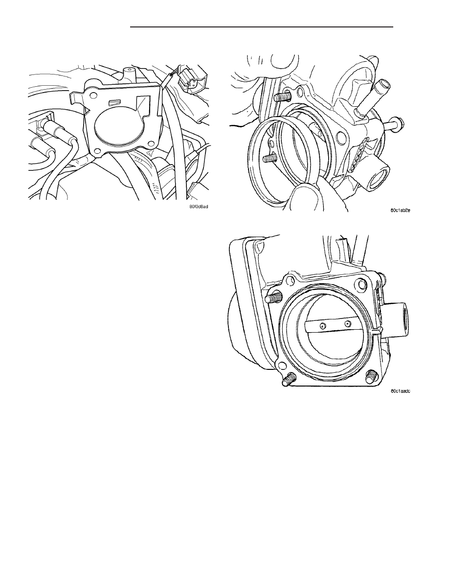
(1) Discard old gasket and clean intake manifold

surface (Fig. 62).

(2) Install the throttle body (Fig. 61).
(3) Install the 3 bolts to the throttle body and

tighten to N·m 11.8 ±20 (105 in. lbs.) (Fig. 60).

(4) Connect the purge hose to the throttle body.
(5) Connect the throttle body inlet hose to the

throttle body and tighten clamp.

(6) Install bracket (Fig. 59).

Fig. 62 THROTTLE BODY GASKET- 2.4L TURBO

Fig. 63 THROTTLE BODY SEAL

Fig. 64 THROTTLE BODY SEAL INSTALLED

14 - 48

FUEL INJECTION

PT

THROTTLE BODY (Continued)

(7) Install the 2 screws for the throttle cable

bracket and tighten to N·m 11.8 ±20 (105 in. lbs.).

(8) If equipped with speed control, install speed

control cable to the throttle cam by sliding clasp in
the hole used for throttle cable.

(9) Install the throttle cable to the throttle body

cam (Fig. 58).

(10) Install the throttle control shield (Fig. 57).
(11) Connect and lock the electrical connectors

from the idle air control motor and throttle position
sensor.

(12) Connect and lock the electrical connector for

the inlet air temperature sensor.

(13) Connect the negative battery cable.

THROTTLE CONTROL CABLE

REMOVAL

(1) Working from the engine compartment, hold

the throttle body throttle lever in the wide open posi-
tion.

(2) Remove the throttle cable from the throttle

body cam.

(3) From inside the vehicle, hold up the pedal and

remove the cable retainer and throttle cable from the
upper end of the pedal shaft.

(4) Remove retainer clip from throttle cable and

grommet at dash panel.

(5) From the engine compartment, pull the throttle

cable and gromment out of the dash panel.

(6) Remove the throttle cable from throttle bracket

by carefully compressing both retaining ears simulta-
neously then gently pull the throttle cable from
throttle bracket or if it is the slide snap design you
have to slide the locking tab out of the hole and then
slide the cable assembly out of the bracket.

INSTALLATION

(1) From the engine compartment, push the hous-

ing end fitting and grommet into the dash panel.In-
stall gromment into the dash panel.

(2) Install the cable housing (throttle body end)

into the cable mounting bracket on the engine.

(3) From inside the vehicle, hold up the pedal and

install throttle cable and cable retainer in the upper
end of the pedal shaft.

(4) At the dash panel, install the cable retainer

clip between the end of the throttle cable fitting and
grommet

(5) From the engine compartment, rotate the

throttle lever wide open and install the throttle
cable.

THROTTLE POSITION SENSOR

DESCRIPTION

The throttle position sensor mounts to the side of

the throttle body (Fig. 66).

OPERATION

The signal represents throttle blade position. As

the position of the throttle blade changes, the resis-
tance of the TPS changes.

The PCM supplies approximately 5 volts to the

TPS. The TPS output voltage (input signal to the
powertrain control module) represents throttle blade
position. The TPS output voltage to the PCM varies
from approximately 0.6 volt at minimum throttle
opening (idle) to a maximum of 4.5 volts at wide open
throttle.

Fig. 65 LOCATING TABS

Fig. 66 Throttle Position Sensor—2.4L Engines

1 - IAC
2 - PCM
3 - TPS

PT

FUEL INJECTION

14 - 49

THROTTLE BODY (Continued)

Along with inputs from other sensors, the PCM

uses the TPS input to determine current engine oper-
ating conditions. The PCM also adjusts fuel injector
pulse width and ignition timing based on these
inputs.

REMOVAL

The throttle position sensor attaches to the side of

the throttle body (Fig. 67) and (Fig. 68).

(1) Remove the air cleaner lid and makeup air

hose. Loosen the clamp and relocate assembly.

(2) Remove the negative battery cable.
(3) Disconnect electrical connector from the throt-

tle position sensor.

(4) Remove

throttle

position

sensor

mounting

screws.

(5) Remove throttle position sensor.

INSTALLATION

The throttle position sensor attaches to the side of

the throttle body (Fig. 67).

(1) The throttle shaft end of the throttle body

slides into a socket in the TPS (Fig. 69). Note to
make sure that the rubber o-ring is in place and
seated around the TPS rotor housing surface. The
socket has two tabs inside it. The throttle shaft rests
against the tabs. When indexed correctly, the TPS
can rotate clockwise a few degrees to line up the
mounting screw holes with the screw holes in the
throttle body. The TPS has slight tension when
rotated into position. If it is difficult to rotate the
TPS into position, reinstall the sensor with the throt-

tle shaft on the other side of the tabs in the socket of
the TPS. Tighten mounting screws to 6.2 N·m (55 in.
lbs.) torque.

(2) After installing the TPS, the throttle plate

should be closed. If the throttle plate is open, install
the sensor on the other side of the tabs in the socket.

(3) Attach electrical connectors to the throttle posi-

tion sensor.

(4) Install the negative battery cable.
(5) Install the air cleaner lid and makeup air hose

and tighten clamp.

Fig. 67 Throttle Position Sensor and Idle Air Control

Motor

1 - IAC
2 - PCM
3 - TPS

Fig. 68 THROTTLE BODY CONNECTIONS - 2.4L

TURBO

1 - Purge Hose
2 - Electrical Connections
3 - Inlet Hose

Fig. 69 Throttle Position Sensor

1 - THROTTLE SHAFT
2 - TABS

14 - 50

FUEL INJECTION

PT

THROTTLE POSITION SENSOR (Continued)

STEERING

TABLE OF CONTENTS

page

page

STEERING

DESCRIPTION - POWER STEERING SYSTEM

. . 1

OPERATION - POWER STEERING SYSTEM

. . . 1

WARNING

WARNINGS AND CAUTIONS

. . . . . . . . . . . . . . 1

DIAGNOSIS AND TESTING

DIAGNOSIS AND TESTING - POWER

STEERING FLOW AND PRESSURE TEST . . . . 1

DIAGNOSIS AND TESTING - STEERING

DIAGNOSIS CHARTS . . . . . . . . . . . . . . . . . . . 3

SPECIFICATIONS - POWER STEERING

FASTENER TORQUE

. . . . . . . . . . . . . . . . . . . . 8

SPECIAL TOOLS

POWER STEERING

. . . . . . . . . . . . . . . . . . . . 9

COLUMN

. . . . . . . . . . . . . . . . . . . . . . . . . . . . . . 10

GEAR

. . . . . . . . . . . . . . . . . . . . . . . . . . . . . . . . . 27

PUMP

. . . . . . . . . . . . . . . . . . . . . . . . . . . . . . . . . 36

STEERING

DESCRIPTION - POWER STEERING SYSTEM

This vehicle comes with power steering as stan-

dard equipment and it is the only steering system
available. The power steering system consists of
these major components:

• POWER STEERING PUMP

• POWER STEERING GEAR

• POWER STEERING FLUID RESERVOIR

• POWER STEERING FLUID PRESSURE HOSE

• POWER STEERING FLUID RETURN HOSE

• POWER STEERING FLUID COOLER
For information on the first two components, refer

to their respective sections within this service man-
ual group. Information on the remaining components
can be found in POWER STEERING PUMP.

OPERATION - POWER STEERING SYSTEM

Turning of the steering wheel is converted into lin-

ear (side-to-side) travel through the meshing of the
helical pinion teeth with the rack teeth within the
steering gear. The lateral travel pushes and pulls the
tie rods to change the direction of the vehicle’s front
wheels.

Power assist steering is provided by a belt driven

rotary type pump. It directs fluid through power
steering fluid hoses to the power steering gear where
it is used to assist the driver’s turning effort.

Manual steering control of the vehicle can be main-

tained if power steering assist is lost. However,
under this condition, steering effort is significantly
increased.

WARNING

WARNINGS AND CAUTIONS

WARNING:

POWER

STEERING

FLUID,

ENGINE

PARTS

AND

EXHAUST

SYSTEM

MAY

BE

EXTREMELY HOT IF ENGINE HAS BEEN RUNNING.
DO NOT START ENGINE WITH ANY LOOSE OR DIS-
CONNECTED HOSES. DO NOT ALLOW HOSES TO
TOUCH HOT EXHAUST MANIFOLD OR CATALYST.

WARNING: FLUID LEVEL SHOULD BE CHECKED
WITH THE ENGINE OFF TO PREVENT PERSONAL
INJURY FROM MOVING PARTS.

CAUTION: When the system is open, cap all open
ends of the hoses, power steering pump fittings or
power steering gear ports to prevent entry of for-
eign material into the components.

DIAGNOSIS AND TESTING

DIAGNOSIS AND TESTING - POWER STEERING
FLOW AND PRESSURE TEST

WARNING:

TO

PREVENT

PERSONAL

INJURY,

SAFETY GOGGLES SHOULD BE WORN AT ALL
TIMES WHILE PERFORMING ANY TEST PROCE-
DURES ON THE POWER STEERING SYSTEM.

The following procedure is to be used to test the

operation of the power steering system on this vehi-
cle. This test will provide the flow rate of the power
steering pump along with the maximum relief pres-
sure. This test is to be performed any time a power

PT

STEERING

19 - 1


Content   ..  743  744  745  746   ..