Chrysler PT Cruiser. Manual - part 741


  Index      Chrysler     Chrysler PT Cruiser - service repair manual 2005 year


Search            


Content   ..  739  740  741  742   ..


Chrysler PT Cruiser. Manual - part 741


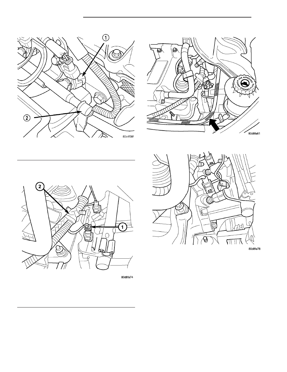
(4) Disconnect the electrical connectors from the

fuel injectors (Fig. 17)

(5) Remove the wiring harness from the fuel rail

brackets.

(6) Remove the fuel line from the fuel rail (Fig.

18).

(7) Remove the 2 bolts to the fuel rail at the lower

manifold.

(8) Remove the fuel rail (Fig. 19)

REMOVAL - 2.4L TURBO

WARNING: RELEASE FUEL SYSTEM PRESSURE
BEFORE SERVICING FUEL SYSTEM COMPONENTS.
SERVICE VEHICLES IN WELL VENTILATED AREAS
AND AVOID IGNITION SOURCES. NEVER SMOKE
WHILE

SERVICING

THE

VEHICLE.

THIS

MAY

RESULT IN PERSONAL INJURY OR DEATH.

(1) Release the fuel system pressure. Refer to Fuel

System Pressure Release procedure in this section.

(2) Disconnect the negative battery cable.
(3) Disconnect the throttle body inlet hose (Fig. 20)

and remove from throttle body.

(4) Disconnect the purge hose from the throttle

body (Fig. 20).

Fig. 16 Fuel Rail

1 - FUEL INJECTOR
2 - FUEL TEST PORT

Fig. 17 INJECTOR CONNECTOR AND WIRING

HARNESS

1 - FUEL INJECTOR ELECTRICAL CONNECTOR
2 - WIRING HARNESS

Fig. 18 FUEL LINE

Fig. 19 FUEL RAIL AND FUEL INJECTOR

14 - 32

FUEL INJECTION

PT

FUEL INJECTOR (Continued)

(5) Unlock and disconnect the electrical connection

at the throttle body (Fig. 20).

(6) Remove the throttle control shield (Fig. 21).

(7) Remove the throttle and speed control cables

from the throttle body.

(8) Remove the cables from the throttle body

bracket.

(9) Unlock and disconnect the MAP sensor electri-

cal connector (Fig. 22).

(10) Remove the vacuum lines from the rear of the

intake manifold (Fig. 23).

(11) Remove the 5 bolts from the front of the

intake manifold.

(12) Remove the 2 bolts from the rear of the intake

manifold (Fig. 23).

(13) Remove the intake manifold. Cover the lower

intake manifold openings (Fig. 24).

Fig. 20 THROTTLE BODY CONNECTIONS - 2.4L

TURBO

1 - Purge Hose
2 - Electrical Connections
3 - Inlet Hose

Fig. 21 THROTTLE CONTROL SHIELD - 2.4L TURBO

Fig. 22 MAP SENSOR - 2.4L TURBO

Fig. 23 VACUUM LINES - 2.4L TURBO

PT

FUEL INJECTION

14 - 33

FUEL INJECTOR (Continued)

(14) Drain the Coolant system, refer to the Cooling

section for more information.

(15) Move the upper radiator hose clamp (Fig. 25),

so that the hose can be rotated up and out of the
way.

(16) Remove the 2 small hoses from the thermo-

stat housing (Fig. 26).

(17) Remove the 2 bolts from the thermostat hous-

ing (Fig. 27)and rotate the assembly up and out of
the way (Fig. 28).

NOTE: WRAP SHOP TOWELS AROUND HOSE TO
CATCH ANY GASOLINE SPILLAGE.

Fig. 24 LOWER INTAKE MANIFOLD - 2.4L TURBO

Fig. 25 UPPER RADIATOR HOSE CLAMP - 2.4L

TURBO

Fig. 26 SMALL HOSES AT HOUSING - 2.4L TURBO

Fig. 27 THERMOSTAT HOUSING - 2.4L TURBO

14 - 34

FUEL INJECTION

PT

FUEL INJECTOR (Continued)

(18) Disconnect the fuel line from the fuel rail

(Fig. 29). Refer to the Quick-Connect Fittings in this
section.

(19) Unlock and disconnect the electrical connec-

tors from the fuel injectors.

(20) Remove the wiring harness from the fuel rail

(Fig. 30).

(21) Remove the 2 bolts from the fuel rail (Fig. 30).

(22) Remove the fuel rail and injectors from the

intake manifold (Fig. 31).

(23) Remove the fuel injector from the fuel rail.

Fig. 28 HOSE AND HOUSING ROTATED - 2.4L

TURBO

Fig. 29 FUEL LINE CONNECTION - 2.4L TURBO

Fig. 30 FUEL RAIL - 2.4L TURBO

Fig. 31 FUEL RAIL & INJECTORS - 2.4L TURBO

PT

FUEL INJECTION

14 - 35

FUEL INJECTOR (Continued)


Content   ..  739  740  741  742   ..