Chrysler PT Cruiser. Manual - part 487


  Index      Chrysler     Chrysler PT Cruiser - service repair manual 2005 year


Search            


Content   ..  485  486  487  488   ..


Chrysler PT Cruiser. Manual - part 487


(4) Raise vehicle and support
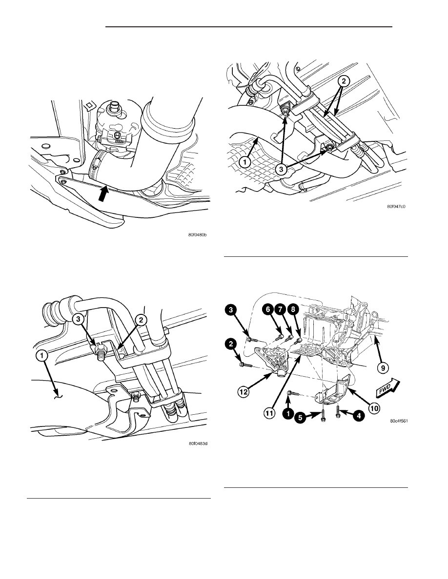
(5) Remove the inner cooler lower hose from the

inner cooler (Fig. 13).

(6) Remove the nuts that hold the lower inner

cooler tube (Fig. 14).

(7) Remove the studs that hold the power steering

lines (Fig. 14).

(8) Loosen and relocate the power steering lines

(Fig. 15).

(9) Remove the Structural Collar (Fig. 16), refer to

the Engine, Structural Collar Removal and Installa-
tion section.

(10) Unlock and disconnect the solenoid electrical

connector.

(11) Disconnect and remove the positive battery

cable.

(12) Remove the lower starter bolt.
(13) Remove starter (Fig. 17).

Fig. 13 INNER COOLER LOWER MOUNTING - 2.4L

TURBO

Fig. 14 INNER COOLER LOWER TUBE MOUNTING -

2.4L TURBO

1 - Lower Inner Cooler Tube
2 - Power Steering Line Brackets
3 - Studs

Fig. 15 POWER STEERING LINE MOUNTING - 2.4L

TURBO

1 - Lower Inner Cooler Tube
2 - Power Steering Lines
3 - Mounting Studs

Fig. 16 Structural Collar and Bending Strut—

(Automatic Transaxle Equipped)

1–8 – BOLT TIGHTENING SEQUENCE
9 – TRANSAXLE
10 – COLLAR
11 – OIL PAN
12 – STRUT

8F - 46

STARTING

PT

STARTER MOTOR (Continued)

INSTALLATION

INSTALLATION - 1.6L

(1) Install the starter through the wheel well (Fig.

6).

(2) Install the lower mounting bolt.
(3) Install the upper mounting bolts.
(4) Push the spring clip that holds the heat shield

for the starter back on the starter solenoid (Fig. 5).

(5) Connect the battery cable (Fig. 4) and solenoid

electrical connectors (Fig. 3) to the starter.

(6) Install the exhaust manifold support bracket

(Fig. 2).

(7) Lower vehicle.
(8) Connect the negative battery cable.
(9) Install air cleaner cover.

INSTALLATION - 2.2L DIESEL

(1) Install starter (Fig. 8).
(2) Install the upper mounting bolt.
(3) Install the lower mounting bolt and ground

cable.

(4) Connect

the

battery

cable

to

the

starter

(Fig. 9).

(5) Connect the electrical connectors to the starter

(Fig. 9).

(6) Install the radiator to vehicle.
(7) Install radiator to inner cooler, make sure the 2

lower mounting tabs (Fig. 7) lock into the radiator
brackets. These tabs are on the bottom of the inner
cooler and lock into the bottom of the radiator.

(8) Install the 4 upper bolts for the inner cooler

mounting to radiator.

(9) Connect the electrical connector for the radia-

tor fan.

(10) Install the upper radiator hose.
(11) Raise vehicle and support.
(12) Install the 2 lower bolts for the inner cooler

mounting to radiator.

(13) Install the lower radiator hose.
(14) Install the underbody plate (skid plate), refer

to the Body section for more information.

(15) Lower vehicle.
(16) Install ambient temperature sensor.
(17) Install the upper radiator crossmember.
(18) Install the hood seal, refer to the Body section

for more information.

(19) Install the front grill, refer to the Body section

for more information.

(20) Connect the negative battery cable.
(21) Fill radiator, refer to the Cooling section for

more information.

INSTALLATION - 2.0/2.4L

(1) Reinstall

starter

motor

into

vehicle

lower

engine compartment.

(2) Install starter motor mounting bolts and torque

to 54 N·m (40 ft. lbs.).

(3) Connect starter motor wiring. Torque solenoid

battery cable nut to 10 N·m (90 in. lbs.).

(4) Install

Engine

Structural

Collar.

Refer

to

Engine, Structural Collar Removal and Installation.

CAUTION:
The torque procedure for the structural collar must
be followed, as damage to the oil pan or collar
could occur.

(5) Lower vehicle from hoist.
(6) Reconnect battery negative cable.
(7) Reinstall air cleaner box cover.
(8) Verify operation of vehicle and systems.
(9) Close hood and remove from hoist.

INSTALLATION - STARTER 2.4L TURBO

(1) Install starter (Fig. 17).
(2) Install the lower starter bolt and tighten bolt

to 54 N·m (40 ft. lbs.).

(3) Connect the positive battery cable and tighten

nut to 10 N·m ( 90 in. lbs.).

(4) Connect and lock the solenoid electrical connec-

tor.

(5) Install the Structural Collar, refer to the

Engine, Structural Collar Removal and Installation
section (Fig. 16).

(6) Locate the power steering lines.
(7) Install the studs that hold the power steering

lines and tighten to 61 N·m (45 ft. lbs.).

(8) Tighten nuts that hold the inner cooler lower

tube.

(9) Install the inner cooler lower hose to the inner

cooler and tighten clamp (Fig. 14).

Fig. 17 STARTER REMOVAL/INSTALLATION - 2.4L

TURBO

PT

STARTING

8F - 47

STARTER MOTOR (Continued)

(10) Lower vehicle.
(11) Pushing the inner cooler hose up and out of

the way and install the upper starter bolt and
ground wire (Fig. 12) and tighten bolt to 54 N·m (40
ft. lbs.).

(12) Install the air cleaner box.
(13) Tighten air cleaner hose clamp
(14) Connect the negative battery cable.

8F - 48

STARTING

PT

STARTER MOTOR (Continued)

HEATED SYSTEMS

TABLE OF CONTENTS

page

page

HEATED GLASS . . . . . . . . . . . . . . . . . . . . . . . . . . . 1
HEATED MIRRORS . . . . . . . . . . . . . . . . . . . . . . . . . 7

HEATED SEAT SYSTEM . . . . . . . . . . . . . . . . . . . . . 8

HEATED GLASS

TABLE OF CONTENTS

page

page

HEATED GLASS

DESCRIPTION

. . . . . . . . . . . . . . . . . . . . . . . . . . 1

OPERATION

. . . . . . . . . . . . . . . . . . . . . . . . . . . . 1

DIAGNOSIS AND TESTING

REAR WINDOW DEFOGGER SYSTEM

. . . . . . 2

REAR WINDOW DEFOGGER SWITCH

DESCRIPTION

. . . . . . . . . . . . . . . . . . . . . . . . . . 3

OPERATION

. . . . . . . . . . . . . . . . . . . . . . . . . . . . 3

DIAGNOSIS AND TESTING

REAR WINDOW DEFOGGER SWITCH

. . . . . . 3

REAR WINDOW DEFOGGER GRID

STANDARD PROCEDURE

GRID LINE AND TERMINAL REPAIR

. . . . . . . . 5

HEATED GLASS

DESCRIPTION

CAUTION: Grid lines can be damaged or scraped
off with sharp instruments. Care should be taken in
cleaning

glass

or

removing

foreign

materials,

decals or stickers. Normal glass cleaning solvents
or hot water used with rags or toweling is recom-
mended.

The rear window defogger system, also known as

electrical backlight (EBL), consists of two vertical bus
bars and a series of grid lines fired onto the inside
surface of the rear window.

The EBL system is turned ON or OFF by a control

switch and a timing circuit, which are combined into
a single push-button switch located on the accessory
switch bezel (Fig. 1) at the center of the instrument
panel (Refer to 8 - ELECTRICAL/HEATED GLASS/
DEFOGGER SWITCH - DESCRIPTION).

Circuit protection is provided by a fuse located in

the power distribution center (PDC) for the heated
grid circuit, and by a fuse in the junction block (JB)
for the control circuit.

OPERATION

The electric backlight (EBL) system is controlled

by a momentary switch located in the accessory
switch bezel on the instrument panel. When the
defogger switch for the EBL system is pressed to the
On position, current is directed to the rear defogger
grid lines and the heated power mirrors (if equipped).
The heated grid lines heat the glass to help clear the
rear window and side mirror surfaces of fog or frost.

An amber indicator in the defogger switch will illu-

minate to indicate when the EBL system is turned
on. The rear window defogger switch contains the
EBL system control circuitry including the timer
logic and the defogger relay.

NOTE: The EBL system turns off automatically after
10 minutes of initial operation. Each following acti-
vation cycle of the EBL system will last five min-
utes.

The EBL system will be automatically turned off

after a programmed time interval of about ten min-
utes. After the initial time interval has expired, if the
defogger switch is turned on again during the same
ignition cycle, the EBL system will automatically
turn off after about five minutes.

PT

HEATED SYSTEMS

8G - 1


Content   ..  485  486  487  488   ..