Chrysler PT Cruiser. Manual - part 426
REMOVAL
REMOVAL - LHD
NOTE: Before proceeding, (Refer to 5 - BRAKES -
WARNING) (Refer to 5 - BRAKES - CAUTION).
(1) Disconnect negative (ground) cable from the
battery and isolate the cable.
(2) Remove the master cylinder. (Refer to 5 -
BRAKES/HYDRAULIC/MECHANICAL/MASTER
CYLINDER - REMOVAL)
(3) If the vehicle is equipped with ABS, remove the
integrated control unit (ICU). (Refer to 5 - BRAKES/
HYDRAULIC/MECHANICAL/ICU
(INTEGRATED
CONTROL UNIT) - REMOVAL)
(4) Disconnect the vacuum hoses from the check
valve on the power brake booster (Fig. 109), but do
not remove the check valve from power brake
booster.
(5) Inside the vehicle, remove the silencer pad
below the knee blocker.
(6) Fold down and remove the knee blocker.
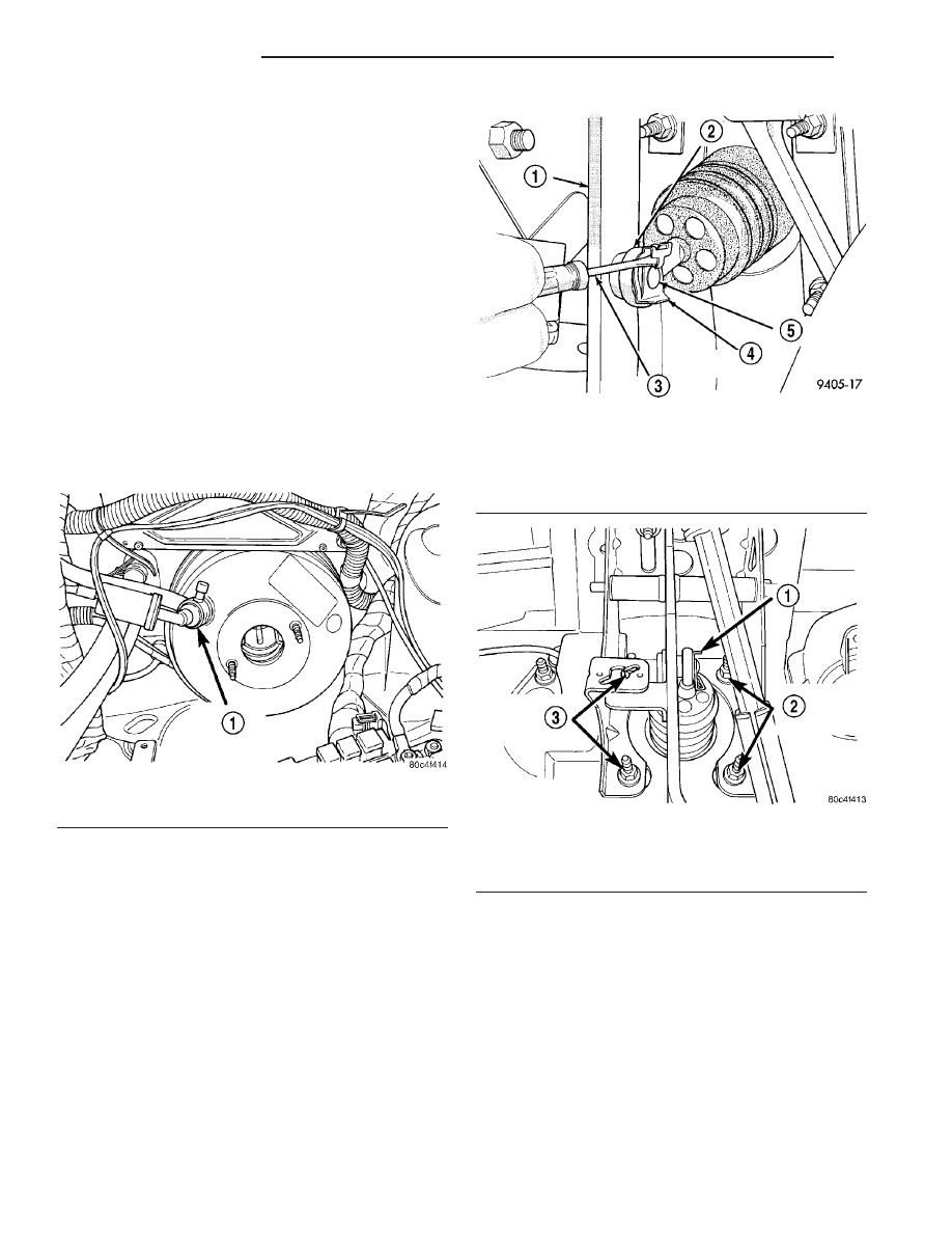
(7) Locate the brake pedal-to-power brake booster
input rod attachment under the instrument panel.
Position a small screwdriver under the center tang of
the retaining clip (Fig. 110). Rotate the screwdriver
enough to allow the retaining clip tang to pass over
the end of the brake pedal pin. Remove the clip.
CAUTION: Discard the used retaining clip, it is not
to be reused. Replace the clip with a new one on
reassembly.
(8) Remove the four nuts attaching the power
brake booster to the instrument panel (Fig. 111). The
nuts are accessible from under the instrument panel
in the area of the brake pedal bracket.
(9) Slide the power brake booster forward until
mounting studs clear the instrument panel, then
remove it from the vehicle.
REMOVAL - RHD
NOTE: Before proceeding, (Refer to 5 - BRAKES -
WARNING) (Refer to 5 - BRAKES - CAUTION).
(1) Disconnect negative (ground) cable from the
battery and isolate the cable.
(2) Using a R-134a refrigerant recovery machine,
remove the refrigerant from the A/C system. (Refer to
Fig. 109 Vacuum Check Valve
1 - VACUUM CHECK VALVE
Fig. 110 Retaining Clip
1 - BRAKE PEDAL
2 - INPUT ROD
3 - SCREWDRIVER
4 - RETAINING CLIP
5 - BRAKE PEDAL PIN
Fig. 111 Power Brake Booster Mounting
1 - CLIP
2 - BOOSTER MOUNTING NUTS
3 - BOOSTER MOUNTING NUTS
5 - 56
BRAKES - BASE
PT
POWER BRAKE BOOSTER (Continued)