Chrysler PT Cruiser. Manual - part 405


  Index      Chrysler     Chrysler PT Cruiser - service repair manual 2005 year


Search            


Content   ..  403  404  405  406   ..


Chrysler PT Cruiser. Manual - part 405


DIAGNOSIS AND TESTING - SUSPENSION AND STEERING

CONDITION

POSSIBLE CAUSES

POTENTIAL CORRECTIONS

Front End Whine On Turns

1. Defective Wheel Bearing

1. Replace Wheel Bearing

2. Incorrect Wheel Alignment

2. Check And Reset Wheel Alignment

3. Worn Tires

3. Replace Tires

Front End Growl Or
Grinding On Turns

1. Defective Wheel Bearing

1. Replace Wheel Bearing

2. Engine Mount Grounding
Against Frame Or Body Of Vehicle.

2. Check For Motor Mount Hitting Frame
Rail And Reposition Engine As Required

3. Worn Or Broken C/V Joint

3. Replace C/V Joint

4. Loose Wheel Lug Nuts

4. Verify Wheel Lug Nut Torque

5. Incorrect Wheel Alignment

5. Check And Reset Wheel Alignment

6. Worn Tires

6. Replace Tires

Front End Clunk Or Snap
On Turns

1. Loose Wheel Lug Nuts

1. Verify Wheel Lug Nut Torque

2. Worn Or Broken C/V Joint

2. Replace C/V Joint

3. Worn Or Loose Tie Rod Or Ball
Joint

3. Tighten Or Replace Tie Rod End Or Ball
Joint

4. Worn Control Arm Bushing

4. Replace Control Arm Bushing

5. Loose Sway Bar Or Upper Strut
Attachment

5. Tighten Sway Bar Or Upper Strut
Attachment To Specified Torque
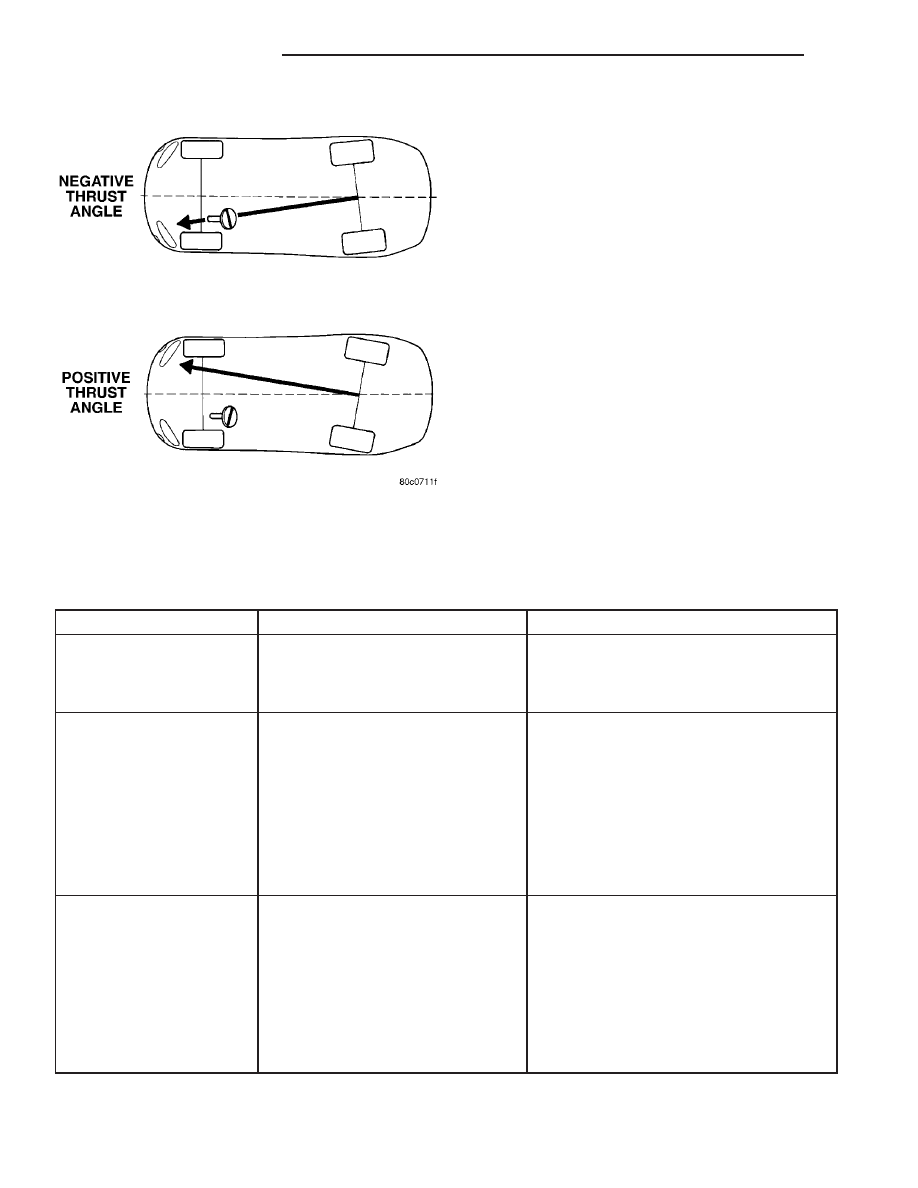
Fig. 6 Thrust Angle

2 - 56

WHEEL ALIGNMENT

PT

WHEEL ALIGNMENT (Continued)

CONDITION

POSSIBLE CAUSES

POTENTIAL CORRECTIONS

Front End Whine With
Vehicle Going Straight At A
Constant Speed

1. Defective Wheel Bearing

1. Replace Wheel Bearing

2. Incorrect Wheel Alignment

2. Check And Reset Wheel Alignment

3. Worn Tires

3. Replace Tires

Front End Growl Or
Grinding With Vehicle
Going Straight At A
Constant Speed

1. Engine Mount Grounding

1. Reposition Engine As Required

2. Worn Or Broken C/V Joint

2. Replace C/V Joint

Front End Whine When
Accelerating Or
Decelerating

1. Worn Or Defective Transaxle
Gears Or Bearings

1. Replace Transaxle Gears Or Bearings

Front End Clunk When
Accelerating Or
Decelerating

1. Worn Or Broken Engine Mount

1. Replace Engine Mount

2. Worn Or Defective Transaxle
Gears Or Bearings

2. Replace Transaxle Gears Or Bearings

3. Loose Wheel Lug Nuts

3. Verify Wheel Lug Nut Torque

4. Worn Or Broken C/V Joint

4. Replace C/V Joint

5. Worn Or Loose Ball Joint

5. Tighten Or Replace Ball Joint

6. Worn Or Loose Control Arm
Bushing

6. Tighten To Specified Torque Or Replace
Control Arm Bushing

7. Loose Crossmember Bolts

7. Tighten Crossmember Bolts To Specified
Torque

Road Wander

1. Incorrect Tire Pressure

1. Inflate Tires To Rcommended Pressure

2. Incorrect Front Or Rear Wheel Toe

2. Check And Reset Front Wheel Toe

3. Worn Wheel Bearings

3. Replace Wheel Bearing

4. Worn Control Arm Bushings

4. Replace Control Arm Bushing

5. Excessive Friction In Steering
Gear

5. Replace Steering Gear

6. Excessive Friction In Steering
Shaft Coupling

6. Replace Steering Coupler

7. Excessive Friction In Strut Upper
Bearing

7. Replace Strut Bearing

Lateral Pull

1. Unequal Tire Pressure

1. Inflate All Tires To Recommended
Pressure

2. Radial Tire Lead

2. Perform Vehicle Lead Diagnosis And
Correction Procedure - Refer To Tires And
Wheels

3. Incorrect Front Wheel Camber

3. Check And Reset Front Wheel Camber

4. Power Steering Gear Imbalance

4. Replace Power Steering Gear

5. Wheel Braking

5. Correct Braking Condition Causing
Lateral Pull

PT

WHEEL ALIGNMENT

2 - 57

WHEEL ALIGNMENT (Continued)

CONDITION

POSSIBLE CAUSES

POTENTIAL CORRECTIONS

Excessive Steering Free
Play

1. Incorrect Steering Gear
Adjustment

1. Adjust Or Replace Steering Gear

2. Worn Or Loose Tie Rod Ends

2. Replace Or Tighten Tie Rod Ends

3. Loose Steering Gear Mounting
Bolts

3. Tighten Steering Gear Bolts To The
Specified Torque

4. Loose Or Worn Steering Shaft
Coupler

4. Replace Steering Shaft Coupler

Excessive Steering Effort

1. Low Tire Pressure

1. Inflate All Tires To Recommended
Pressure

2. Lack Of Lubricant In Steering
Gear

2. Replace Steering Gear

3. Low Power Steering Fluid Level

3. Fill Power Steering Fluid Reservoir To
Correct Level

4. Loose Power Steering Pump Belt

4. Check and replace automatic belt
tensioner as necessary. If drive belt is worn
or glazed, replace belt.

5. Lack Of Lubricant In Steering Ball
Joints

5. Lubricate Or Replace Steering Ball Joints

6. Steering Gear Malfunction

6. Replace Steering Gear

7. Lack Of Lubricant In Steering
Coupler

7. Replace Steering Coupler

STANDARD PROCEDURE

STANDARD PROCEDURE - CURB HEIGHT
MEASUREMENT

The wheel alignment is to be checked and all align-

ment adjustments made with the vehicle at its
required curb height specification.

Vehicle height is to be checked with the vehicle on

a flat, level surface, preferably a vehicle alignment
rack. The tires are to be inflated to the recommended
pressure. All tires are to be the same size as stan-
dard equipment. Vehicle height is checked with the
fuel tank full of fuel, and no passenger or luggage
compartment load.

Vehicle height is not adjustable. If the measure-

ment is not within specifications, inspect the vehicle
for bent or weak suspension components. Compare
the parts tag on the suspect coil spring(s) to the
parts book and the vehicle sales code, checking for a
match. Once removed from the vehicle, compare the

coil spring height to a correct new or known good coil
spring. The heights should vary if the suspect spring
is weak.

NOTE: Prior to reading the curb height measure-
ment, the front an rear of the vehicle should be
jounced. Induce jounce by grasping the center of
the rear, then front bumper (or fascia) and jouncing
the vehicle an equal number of times. Release the
bumper at the bottom of the jounce cycle.

(1) Measure from the edge of the wheel opening

fender lip directly above the wheel center (spindle)
down to the floor or alignment rack surface.

(2) When measuring, maximum left-to-right differ-

ential is not to exceed 10 mm (0.39 in.).

(3) Compare the measurements to specifications

listed in the following CURB HEIGHT SPECIFICA-
TIONS chart.

2 - 58

WHEEL ALIGNMENT

PT

WHEEL ALIGNMENT (Continued)

CURB HEIGHT SPECIFICATIONS

VEHICLE

FRONT

REAR

ALL

695 mm ± 8 mm

716 mm ± 8 mm

27.37 in. ± 0.32 in.

28.27 in. ± 0.32 in.

STANDARD PROCEDURE - WHEEL ALIGNMENT

PRE-WHEEL ALIGNMENT INSPECTION

CAUTION: If during the inspection the front suspen-
sion crossmember shows any sign of impact dam-
age, the steering column lower coupling must be
inspected.

(Refer

to

19

-

STEERING/COLUMN/

STEERING COUPLING - DIAGNOSIS AND TESTING)

Before any attempt is made to change or correct

the wheel alignment, the following inspection and
necessary corrections must be made to the vehicle to
ensure proper alignment.

(1) Be sure the fuel tank is full of fuel. If the fuel

tank is not full, the reduction in weight will affect
the curb height of the vehicle and the alignment
specifications.

(2) The passenger and luggage compartments of

the vehicle should be free of any load that is not fac-
tory equipment.

(3) Check the tires on the vehicle. The tires are to

be inflated to the recommended air pressure. All tires
must be the same size and in good condition with
approximately the same tread wear.

(4) Check the front tire and wheel assemblies for

excessive radial runout.

(5) Inspect all suspension component fasteners for

looseness and proper torque.

(6) Inspect the lower front ball joints and all steer-

ing linkage for looseness and any sign of wear or
damage.

(7) Inspect the rubber bushings on all the suspen-

sion components for signs of wear or deterioration. If
any bushings show signs of wear or deterioration,
they should be replaced prior to aligning the vehicle.

(8) Check vehicle curb height to verify it is within

specifications. (Refer to 2 - SUSPENSION/WHEEL
ALIGNMENT - STANDARD PROCEDURE)

WHEEL ALIGNMENT SETUP

(1) Position the vehicle on an alignment rack.
(2) Install all required alignment equipment on

the vehicle, per the alignment equipment manufac-
turer’s instructions. On this vehicle, a four-wheel
alignment is recommended.

NOTE: Prior to reading the vehicle’s alignment
readouts, the front and rear of vehicle should be
jounced. Induce jounce (rear first, then front) by

grasping the center of the bumper and jouncing
each end of vehicle an equal number of times. The
bumper should always be released when vehicle is
at the bottom of the jounce cycle.

(3) Read the vehicle’s current front and rear align-

ment settings. Compare the vehicle’s current align-
ment settings to the vehicle specifications for camber,
caster and toe-in. (Refer to 2 - SUSPENSION/
WHEEL ALIGNMENT - SPECIFICATIONS)

REAR CAMBER AND TOE

Rear camber and rear toe settings on this vehicle

are determined at the time the vehicle is designed,
by the location of the vehicle’s suspension compo-
nents. This is referred to as Net Build. The result is
no required adjustment of camber and toe after the
vehicle is built or when servicing the suspension
components. Thus, when performing a wheel align-
ment, rear camber and toe are not normally consid-
ered

adjustable

angles.

Although

not

normally

considered adjustable, rear camber and toe can be
changed when necessary through the use of specially
designed shims. To install shims, use the following
procedure.

(1) Raise the vehicle until its tires are off the floor

or alignment rack.

(2) Remove the tire and wheel assembly.
(3) Access the spindle mounting bolts following the

Spindle Removal procedure found in Rear Suspen-
sion. (Refer to 2 - SUSPENSION/REAR/SPINDLE -
REMOVAL)

(4) Loosen the four spindle mounting bolts just

enough to slide the adjustment shim in between the
spindle and the axle mounting flange.

NOTE: Each shim is 0.010 in. (0.254 mm) thick. Do
not place more than two shims at any one spindle.

(5) Hook the shim on the mounting bolts utilizing

the slots cut into the shim. Refer to the following list
for shim placement:

• To achieve more positive camber, place the shim

across the two upper mounting bolts.

• To achieve more negative camber, place the shim

across the two lower mounting bolts.

• To achieve more positive toe, place the shim

across the two rearward mounting bolts.

• To achieve more negative toe, place the shim

across the two forward mounting bolts.

PT

WHEEL ALIGNMENT

2 - 59

WHEEL ALIGNMENT (Continued)


Content   ..  403  404  405  406   ..