Chrysler PT Cruiser. Manual - part 399


  Index      Chrysler     Chrysler PT Cruiser - service repair manual 2005 year


Search            


Content   ..  397  398  399  400   ..


Chrysler PT Cruiser. Manual - part 399


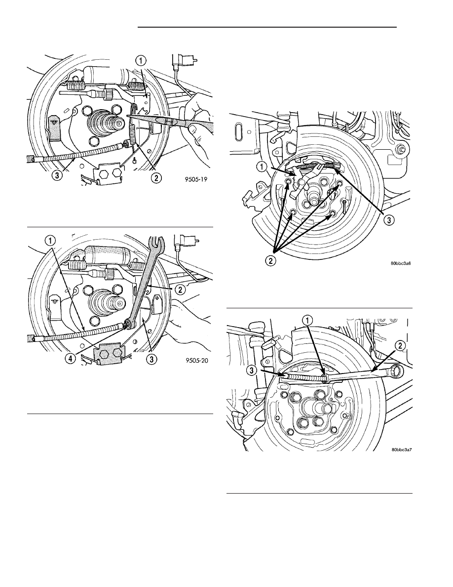
(16) To remove the parking brake cable from the

disc brake adapter on vehicles equipped with rear
disc brakes:

(a) Remove the parking brake actuating lever

from the parking brake cable (Fig. 11).

(b) Remove the parking brake cable from the

rear disc brake adapter. The parking brake cable
can be removed from the disc brake adapter using
a

1

2

inch offset box wrench to compress the locking

fingers on the parking brake cable retainer (Fig.
12).

Fig. 9 Actuating Spring

1 - BRAKE SHOE ADJUSTMENT LEVER
2 - ADJUSTMENT LEVER ACTUATING SPRING
3 - PARK BRAKE CABLE

Fig. 10 Parking Brake Cable Removal

1 - PARK BRAKE CABLE
2 - 1/2

88

WRENCH

3 - REAR BRAKE SUPPORT PLATE
4 - PARK BRAKE CABLE RETAINER

Fig. 11 Parking Brake Actuator Lever

1 - SHOE ACTUATOR LEVER
2 - SHIELD MOUNTING SCREWS
3 - REAR PARKING BRAKE CABLE

Fig. 12 Parking Brake Cable Removal

1 - CABLE RETAINER
2 - OFFSET BOX WRENCH
3 - PARKING BRAKE CABLE

2 - 32

REAR SUSPENSION

PT

AXLE - FRONT WHEEL DRIVE REAR (Continued)

(17) Remove the two bolts on each axle trailing

arm securing the cable and routing brackets to the
arm (Fig. 13).

(18) Pull cable through hole in trailing arm.
(19) On vehicles equipped with antilock brakes,

remove the bolts securing the wheel speed sensor
heads to the disc brake adapters or drum brake sup-
port plates (Fig. 14). Remove the sensors from the
adapters or support plates.

(20) Remove the four bolts securing each brake

shoe support plate (drum brakes) or disc brake
adapter, and spindle to the axle (Fig. 5).

(21) On each side of the vehicle, remove the sup-

port plate or disc brake adapter, and the spindle from
the axle. Hang the support plate out of the way using
a wire hanger or bungee cord.

(22) Remove the bolt securing the watts link bell

crank to the center of the axle (Fig. 15).

(23) If equipped with a rear stabilizer bar, remove

the bolts securing the stabilizer bar cushion retainers
to the rear axle (Fig. 16), then remove the stabilizer
bar from the axle.

(24) Position a transmission jack or equivalent

under the center of the axle raising it enough to sup-
port the axle.

(25) Remove the shock absorber lower mounting

bolts and nuts at the axle (Fig. 15).

(26) Lower the transmission jack until the coil

springs can be removed from the axle.

(27) Remove the coil springs and rubber isolators

(Fig. 15).

(28) Using an awl, scribe a line marking the loca-

tion of the axle trailing arm bracket, side-to-side and
front-to-rear, on the body of the vehicle (Fig. 17).

(29) Remove the bolts securing the trailing arm

forward brackets to the body of the vehicle.

(30) Remove the axle from the vehicle.
(31) To remove the trailing arm forward brackets

from the axle, remove the thru-bolts.

Fig. 13 Cable Routing Bracket Fasteners

1 - CABLE
2 - ARM
3 - FASTENERS

Fig. 14 Wheel Speed Sensor

1 - SHOCK ABSORBER
2 - RIGHT REAR WHEEL SPEED SENSOR

PT

REAR SUSPENSION

2 - 33

AXLE - FRONT WHEEL DRIVE REAR (Continued)

Fig. 15 Rear Suspension

1 - ISOLATORS
2 - JOUNCE BUMPER
3 - SHOCK ABSORBER
4 - WATTS LINK (UPPER)

5 - WATTS LINK (LOWER)
6 - BELL CRANK
7 - AXLE
8 - COIL SPRING

2 - 34

REAR SUSPENSION

PT

AXLE - FRONT WHEEL DRIVE REAR (Continued)

INSPECTION

Verify proper torque of all axle fasteners.
Inspect the axle looking for damage or bending. If

damage is evident, the axle must be replaced.

Inspect for broken or cracked welds at each end of

the twist beam within the axle. Inspect for broken or
cracked welds at each axle trailing arm bushing bore.
If a problem is present, the axle must be replaced.

Inspect the bushings at the leading ends of the

axle trailing arms. Look for damage or deterioration
of the bushings. Make sure the bushings are centered
side-to-side in their bore. If a problem exists, the
bushings must be replaced. They can be replaced sep-
arately from the axle.

INSTALLATION

(1) If removed, install the trailing arm forward

brackets on each side of the axle in the following
way:

(a) From above the axle, place the bracket down

over the axle trailing arm bushing aligning the
hole in the bracket with the center hole in the
bushing (Fig. 15).

(b) From the outboard side of the axle and

bracket, push the thru-bolt through the bracket
and bushing. The trailing arm bracket thru-
bolts must be installed from the outside, in
toward the center of the axle assembly, other-
wise the bolt threaded ends will come in con-
tact with the body of the vehicle upon axle
installation on vehicle.

(c) Install the nut on the inboard end of the nut.

Tighten the nut until the bracket has resistance
when turned, but still moves independent of the
axle bushing. It must be fully tightened later, once
the vehicle is at curb height.
(2) Center the axle beam on the transmission jack

standing at axle removal height.

(3) Swing the trailing arms up aligning the brack-

ets with the scribed marks made upon removal (Fig.
17), then install all eight mounting bolts (four per
side). Thread the bolts in, but do not fully tighten.

(4) Tap the axle trailing arm brackets as necessary

to align the brackets to the scribed marks, then
tighten the bolts to a torque of 54 N·m (40 ft. lbs.).

(5) Install a rubber isolator on each end of the coil

springs wrapping the rubber fingers around the coil
(Fig. 18). Turn the isolators until the rubber abut-
ment butts up against the flat end of the spring coil.

NOTE: Both ends of the coil spring are identical.
Either end of the spring can be the top or bottom.

(6) Place the coil springs on top of the axle spring

perches.

(7) The coil springs require proper orientation to

the body when installed. To do this, turn the coil
springs (along with the rubber isolators) until the
flat end of each upper spring coil lines up with an
imaginary line running parallel with the axle beam
as shown (Fig. 19). Also, make sure that the upper
coils end near the outboard sides of the vehicle and
not 180 degrees of that location.

Fig. 16 Stabilizer Bar Mounting

1 - LINK
2 - STABILIZER BAR
3 - CUSHION
4 - RETAINER

Fig. 17 Marking Bracket Location

1 - SCRIBED LINE
2 - AWL
3 - BRACKET

PT

REAR SUSPENSION

2 - 35

AXLE - FRONT WHEEL DRIVE REAR (Continued)


Content   ..  397  398  399  400   ..