Chrysler PT Cruiser. Manual - part 215


  Index      Chrysler     Chrysler PT Cruiser - service repair manual 2005 year


Search            


Content   ..  213  214  215  216   ..


Chrysler PT Cruiser. Manual - part 215


(4) Install accessory belt splash shield (Fig. 76)

and lower vehicle.

ADJUSTMENTS

ENGINE TORQUE STRUT ADJUSTMENT

The upper and lower torque struts need to be

adjusted together to assure proper engine positioning
and engine mount loading. Whenever a torque strut
bolt(s) is loosened, this procedure must be performed.

(1) Remove accessory drive belt splash shield (Fig.

76).

(2) Remove pencil strut (Fig. 77).
(3) Loosen the upper and lower torque strut

attaching bolt at the suspension crossmember and
shock tower bracket (Fig. 75).

(4) The engine position may now be adjusted by

positioning a suitable floor jack on the forward edge
of the transmission bell housing (Fig. 78).

NOTE: The floor jack must be positioned as shown
in (Fig. 78) to prevent minimal upward lifting of the
engine.

(5) With the engine supported, remove the upper

and lower torque strut attachment bolt(s) at shock
tower bracket and suspension crossmember (Fig. 78).
Verify that the torque struts are free to move within
the shock tower bracket and crossmember. Reinstall
the torque strut bolt(s), but do not tighten.

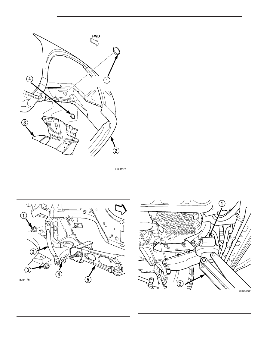
Fig. 76 Splash Shield

1 - RIGHT MOUNT BOLT ACCESS PLUG
2 - FASCIA
3 - SPLASH SHIELD
4 - CRANKSHAFT BOLT ACCESS PLUG

Fig. 77 Pencil Strut

1 - NUT
2 - PENCIL STRUT
3 - NUT
4 - FLAT WASHER
5 - LOWER TORQUE STRUT

Fig. 78 Floor Jack Positioning

1 - WOOD BLOCK
2 - FLOOR JACK

9 - 56

ENGINE

PT

TORQUE STRUT (Continued)

(6) Carefully apply upward force, allowing the

upper engine to rotate rearward until the distance
between the center of the rearmost attaching bolt on
the engine mount bracket (point “A”) and the center
of the hole on the shock tower bracket (point “B”) is
119 mm (4.70 in.) (Fig. 79).

CAUTION: The engine must be held in position with
jack until both the upper and lower torque strut
bolts are tightened.

(7) With the engine held at the proper position,

tighten both the upper and lower torque strut bolts
to 115 N·m (85 ft. lbs.) (Fig. 75).

(8) Remove the floor jack.
(9) Install pencil strut and tighten nuts to 58 N·m

(43 ft. lbs.) (Fig. 77).

(10) Install accessory drive belt splash shield (Fig.

76).

RIGHT MOUNT

REMOVAL

(1) Remove the engine assembly for the required

clearance to access the engine mount (Refer to 9 -
ENGINE - REMOVAL).

NOTE: The right engine mount attaching holes are
slightly oversize to compensate for manufacturing
tolerances. The mount has been set at the manufac-
turing plant for proper powertrain alignment. There-
fore, it is necessary to mark the position of the
mount before the attaching bolts are loosened.

(2) Using a permanent ink marker or equivalent,

mark the position of engine mount to the body frame
rail.

(3) Remove bolts attaching mount to body (Fig.

80).

(4) Remove mount.

INSTALLATION

(1) Position mount into the original position on

body frame rail (Fig. 80).

NOTE: Engine mount must be installed in the origi-
nal position on body frame rail. If mount was not
marked or frame rail was replaced, perform the fol-
lowing procedure.

(2) Perform the following procedure if the mount

position was not previously marked, or the frame rail
was replaced:

(a) Insert new mount loosely in frame rail.
(b) Align the four holes in the mount with the

mating holes in the rail such that the holes are
concentric (frame rail holes centered in the mount
holes).

(c) Using a permanent ink marker or equivalent,

mark the position of engine mount to the body
frame rail while maintaining mounting hole con-
centricity.
(3) Ensure the mount maintains originally marked

position and install mount bolts. Tighten bolts to 28
N·m (250 in. lbs.) (Fig. 80).

(4) Install the engine assembly (Refer to 9 -

ENGINE - INSTALLATION).

Fig. 79 Engine Position Measurement

Fig. 80 Engine Mount—Right

1 - SNUBBER PAD
2 - RIGHT ENGINE MOUNT
3 - BOLTS

PT

ENGINE

9 - 57

TORQUE STRUT (Continued)

LEFT MOUNT

REMOVAL

(1) Disconnect negative battery cable.
(2) Remove air cleaner assembly.
(3) Remove bolts attaching the power distribution

center (PDC) bracket to left mount and battery tray
(Fig. 81).

(4) Support transaxle with a suitable jack.
(5) Remove mount to transaxle bolts (Fig. 82).
(6) Remove left mount bracket to body frame rail

fasteners (Fig. 82).

(7) Remove mount.

INSTALLATION

(1) Install engine mount bracket to body frame rail

and tighten fasteners to 28 N·m (250 in. lbs.) (Fig.
82).

(2) Position engine/transaxle for installation of

mount to transaxle bolts. Install and tighten bolts to
68 N·m (50 ft. lbs.) (Fig. 82).

(3) Remove jack from under transaxle.
(4) Install bolts attaching the power distribution

center (PDC) bracket to left mount and battery tray
(Fig. 81).

(5) Install air cleaner assembly.
(6) Connect negative battery cable.

Fig. 81 PDC Brackett Attaching Bolts - Typical

1 - PDC
2 - PDC BRACKET BOLTS
3 - BATTERY TRAY BOLT

Fig. 82 LEFT MOUNT - TYPICAL

1 - BOLT (2)
2 - MOUNT
3 - BRACKET

9 - 58

ENGINE

PT

FUEL SYSTEM

TABLE OF CONTENTS

page

page

FUEL SYSTEM - 2.2L DIESEL

WARNING

WARNING - HIGH FUEL SYSTEM

PRESSURE . . . . . . . . . . . . . . . . . . . . . . . . . . . 1

WARNING

. . . . . . . . . . . . . . . . . . . . . . . . . . . . 1

DIAGNOSIS AND TESTING

DIAGNOSIS AND TESTING - HIGH

PRESSURE FUEL LINES . . . . . . . . . . . . . . . . . 1

DIAGNOSIS AND TESTING - AIR IN FUEL

SYSTEM . . . . . . . . . . . . . . . . . . . . . . . . . . . . . 2

DIAGNOSIS AND TESTING - INJECTOR

LEAK QUANTITY . . . . . . . . . . . . . . . . . . . . . . . 2

STANDARD PROCEDURE

STANDARD PROCEDURES - CLEANING

FUEL SYSTEM COMPONENTS . . . . . . . . . . . . 3

STANDARD PROCEDURES - DRAINING

WATER FROM FUEL FILTER . . . . . . . . . . . . . . 3

STANDARD PROCEDURE - LOW

PRESSURE FUEL PUMP TEST . . . . . . . . . . . . 3

SPECIAL TOOLS

. . . . . . . . . . . . . . . . . . . . . . . . 5

FUEL DELIVERY

. . . . . . . . . . . . . . . . . . . . . . . . . . 6

FUEL INJECTION

. . . . . . . . . . . . . . . . . . . . . . . . 17

FUEL SYSTEM - 2.2L DIESEL

WARNING

WARNING - HIGH FUEL SYSTEM PRESSURE

WARNING: HIGH-PRESSURE FUEL LINES DELIVER
FUEL UNDER EXTREME PRESSURE FROM THE
INJECTION

PUMP

TO

THE

INJECTORS.

THIS

MAYBE AS HIGH AS 1600BAR (23,200PSI). USE
EXTREME CAUTION WHEN INSPECTING FOR HIGH-
PRESSURE

FUEL

LEAKS.

FUEL

UNDER

THIS

AMOUNT OF PRESSURE CAN PENETRATE SKIN
CAUSING PERSONAL INJURY OR DEATH. INSPECT
HIGH-PRESSURE FUEL LEAKS WITH A SHEET OF
CARDBOARD. WEAR SAFETY GOGGLES AND ADE-
QUATE PROTECTIVE CLOTHING WHEN SERVICING
FUEL SYSTEM.

WARNING

WARNING: UNDER NO CIRCUMSTANCES SHOULD
GASOLINE BE MIXED WITH DIESEL FUEL (NOT
EVEN DURING WINTER). THE HIGH PRESSURE
PUMP IS LUBRICATED BY DIESEL FUEL. IMMEDI-
ATE FUEL SYSTEM DAMAGE MAY OCCUR CAUS-
ING

REPLACEMENT

AND

FLUSHING

OF

THE

COMPLETE DIESEL FUEL SYSTEM. HIGH PRES-
SURE PUMP SEIZURE WILL CAUSE METAL PARTI-
CLES TO SPREAD THROUGH OUT THE FUEL
CIRCUIT. ALL CDI FUEL SYSTEM COMPONENTS
CONNECTED TO THE FUEL CIRCUIT WILL HAVE TO
BE EXCHANGED AND THE LINES FLUSHED.

DIAGNOSIS AND TESTING

DIAGNOSIS AND TESTING - HIGH PRESSURE
FUEL LINES

WARNING: HIGH-PRESSURE FUEL LINES DELIVER
FUEL UNDER EXTREME PRESSURE FROM THE
INJECTION

PUMP

TO

THE

INJECTORS.

THIS

MAYBE AS HIGH AS 1600BAR (23,200PSI). USE
EXTREME CAUTION WHEN INSPECTING FOR HIGH-
PRESSURE

FUEL

LEAKS.

FUEL

UNDER

THIS

AMOUNT OF PRESSURE CAN PENETRATE SKIN
CAUSING PERSONAL INJURY OR DEATH. INSPECT
FOR HIGH-PRESSURE FUEL LEAKS WITH A SHEET
OF CARDBOARD PLACED IN THE SUSPECTED
AREA WHILE THE ENGINE IS NOT RUNNING.
START THE VEHICLE AND ALLOW THE ENGINE TO
RUN FOR A SHORT PERIOD. TURN THE ENGINE
OFF AND INSPECT THE PIECE OF CARDBOARD.
WEAR SAFETY GOGGLES AND ADEQUATE PRO-
TECTIVE CLOTHING WHEN SERVICING FUEL SYS-
TEM.

High-pressure fuel line leaks can cause starting

problems and poor engine performance.

• Turn the engine off.

• Place a piece for cardboard in the suspected area

(Fig. 1).

• Start the engine and allow to run for a short

period.

• Turn the engine off.

• Inspect the cardboard.
If a high-pressure line connection is leaking, coun-

terhold and tighten the connection to specification
then perform this procedure again (Refer to 14 -

PT

FUEL SYSTEM

14 - 1


Content   ..  213  214  215  216   ..