Chrysler New Yorker. Manual - part 341


  Index      Chrysler     Chrysler New Yorker - service repair manual 1997-1999 year


Search            


Content   ..  339  340  341  342   ..


Chrysler New Yorker. Manual - part 341


INSTALLATION

(1) Install LDP to EVAP Canister. (Fig. 9).
(2) Install EVAP canister to Bracket (Fig. 8).
(3) Install 2 nuts to EVAP canister bracket.
(4) Connect hoses.
(5) Install fuel tank refer to Group 14, Fuel Deliv-

ery.

(6) Connect negative battery cable.

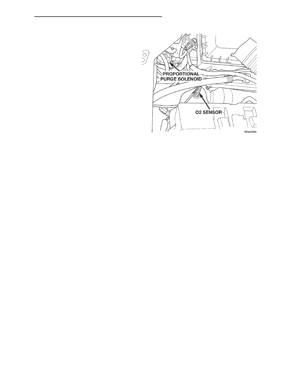
PROPORTIONAL PURGE SOLENOID VALVE

The solenoid attaches to a bracket near the air

cleaner (Fig. 10). The solenoid will not operate unless
it is installed correctly.

REMOVAL

(1) Disconnect electrical connector from solenoid.
(2) Disconnect vacuum tubes from solenoid.
(3) Remove solenoid from bracket.

INSTALLATION

The top of the solenoid has TOP printed on it. The

solenoid will not operate unless it is installed cor-
rectly.

(1) Install solenoid on bracket.

(2) Connect vacuum tube to solenoid.
(3) Connect electrical connector to solenoid.

Fig. 10 Proportional Purge Solenoid Valve

300M

EMISSION CONTROL SYSTEMS

25 - 17

REMOVAL AND INSTALLATION (Continued)

EXHAUST GAS RECIRCULATION (EGR) SYSTEM

INDEX

page

page

DESCRIPTION AND OPERATION

EXHAUST GAS RECIRCULATION (EGR) . . . . . . 18

REMOVAL AND INSTALLATION

EGR TUBE LOWER—2.7L . . . . . . . . . . . . . . . . . 20
EGR TUBE UPPER—2.7L . . . . . . . . . . . . . . . . . . 20

EGR TUBE—3.2/3.5L . . . . . . . . . . . . . . . . . . . . . 21
EGR VALVE—2.7L . . . . . . . . . . . . . . . . . . . . . . . 18
EGR VALVE—3.2/3.5L . . . . . . . . . . . . . . . . . . . . 19

SPECIFICATIONS

TORQUE . . . . . . . . . . . . . . . . . . . . . . . . . . . . . . 21

DESCRIPTION AND OPERATION

EXHAUST GAS RECIRCULATION (EGR)

The EGR valve consists of three major components.

First there is the pintle, valve seat, and housing
which contains and regulates the gas flow. Second
there is the armature, return spring, and solenoid
coil to provide the operating force to regulate the
flow by changing the pintle position. The solenoid coil
assembly is in parallel with a diode and connects to
the two connectors in the connector assembly. The
third major component which senses pintle position
and is connected to the three connectors in the elec-
trical connector.

The exhaust gas recirculation flow is determined

by the engine controller. For a given set of conditions,
the engine controller knows the ideal exhaust gas
recirculation flow to optimize NOx and fuel economy
as a function of the pintle position. Pintle position is
obtained from the position sensor and the engine con-
troller by adjusting the duty cycle of 128 Hz power
supplied to the solenoid coil to obtain the correct
position.

REMOVAL AND INSTALLATION

EGR VALVE—2.7L

REMOVAL

(1) Disconnect negative battery cable.
(2) Remove air inlet tube and resonator.
(3) Remove throttle cable bracket and reposition.
(4) Remove EGR tube mounting screws at intake

manifold plenum.

(5) Disconnect electrical connector from solenoid.
(6) The EGR valve attaches to the rear of the right

cylinder head.

(7) Remove EGR upper tube screws at EGR valve.
(8) Remove EGR valve mounting screws.
(9) Remove

screws

from

EGR

lower

tube

at

exhaust manifold.

(10) Remove EGR valve and lower tube as an

assembly.

(11) Clean gasket surfaces. Discard old gasket. If

necessary, clean EGR passages.

INSTALLATION

(1) Loosely install EGR valve and lower tube, use

a new gasket between tube and EGR valve.

(2) Install EGR valve to rear of Cylinder head, do

not tighten screws.

(3) Loosely install screws to lower EGR tube to

exhaust manifold

(4) Install rubber silicone seals on intake manifold

end of EGR tube.

(5) Install upper tube into the intake manifold,

being careful to be sure silicone rubber seals is cor-
rectly installed and undamaged..

(6) Install new gasket between the EGR valve and

tube and install bolts.

(7) Tighten the EGR upper tube to intake manifold

plenum screws to 9 N·m (80 in. lbs.) torque.

(8) Tighten the EGR tube’s to EGR valve bolts to

11 N·m (95 in. lbs.) torque.

(9) Tighten EGR lower tube to exhaust manifold

screws to 22 N·m (200 in. lbs.) torque.

(10) Tighten EGR valve to cylinder head screws to

22 N·m (200 in. lbs.) torque.

(11) Attach electrical connector to solenoid.
(12) Install the throttle cable bracket to intake

manifold.

(13) Install air inlet tube and resonator.
(14) Connect negative battery cable.

25 - 18

EMISSION CONTROL SYSTEMS

300M

EGR VALVE—3.2/3.5L

The EGR tube attaches to the bottom of the intake

manifold plenum beside the throttle body (Fig. 2).

REMOVAL

(1) Disconnect negative battery cable.
(2) Remove air inlet tube and resonator.
(3) Remove EGR tube mounting clips at intake

manifold plenum (Fig. 3).

(4) Remove Intake Plenum, refer to Group 11

Intake and Exhaust Systems.

(5) Remove the fuel rail, refer to Group 14 Fuel

Delivery.

(6) Disconnect

electrical

connector

from

EGR

valve.

(7) Remove EGR tube mounting screws at EGR

valve.

When removing EGR upper tube assembly being

careful not to drop the silicone rubber seals in the
intake manifold. Clean gasket surfaces on the EGR
valve. Note that any loose dirt can lodge between the
pintle and the seat and cause valve leakage that will
give a rough idle and depressed manifold vacuum.

(8) Remove EGR tube.
(9) The EGR valve attaches to the rear of the right

cylinder head.

(10) Remove EGR valve mounting screws.
(11) Clean gasket surfaces. Discard old gasket. If

necessary, clean EGR passages.

INSTALLATION

(1) Loosely install EGR valve and new gasket on

cylinder head.

(2) Using new gaskets, loosely install the EGR

tube and mounting screws. Make sure that the tube
is parallel with the mounting surface of the EGR
valve (Fig. 4).

Fig. 1 EGR Valve—2.7 L

Fig. 2 Intake Manifold EGR Port Location

Fig. 3 EGR Tube

Fig. 4 Mounting the EGR Tube to EGR Valve

300M

EMISSION CONTROL SYSTEMS

25 - 19

REMOVAL AND INSTALLATION (Continued)

(3) Tighten the EGR tube to EGR valve screws to

11 N·m (95 in. lbs.) torque.

(4) Install rubber silicone seals on intake manifold

end of EGR tube.

(5) Attach electrical connector to solenoid.
Install fuel rail, refer to Group 14, Fuel Delivery.
(6) Install upper tube into the intake manifold,

being careful to be sure silicone rubber seals is cor-
rectly installed and undamaged. Install Intake Ple-
num refer to Group 11, Intake and Exhaust System.

(7) Install clips for the EGR tube to intake mani-

fold plenum.

(8) Tighten EGR valve to cylinder head screws to

22 N·m (200 in. lbs.) torque.

(9) Install air inlet tube and resonator.
(10) Connect negative battery cable.

EGR TUBE UPPER—2.7L

The EGR tube attaches to the intake manifold ple-

num on both sides of the throttle body and the EGR
valve (Fig. 5).

REMOVAL

(1) Disconnect negative battery cable.
(2) Remove air inlet tube and resonator.
(3) Remove throttle cable bracket and reposition.
(4) Remove EGR tube mounting screws at intake

manifold plenum (Fig. 6).

(5) Remove EGR tube mounting screws at EGR

valve.

(6) Remove EGR upper tube.
(7) When removing EGR upper tube assembly

being careful not to drop the silicone rubber seals in
the intake manifold. Clean gasket surfaces on the
EGR valve. Note that any loose dirt can lodge
between the pintle and the seat and cause valve

leakage that will give a rough idle and depressed
manifold vacuum.

INSTALLATION

(1) Install rubber silicone seals on intake manifold

end of EGR tube.

(2) Install upper tube into the intake manifold,

being careful to be sure silicone rubber seals is cor-
rectly installed and undamaged..

(3) Install new gasket between the EGR valve and

tube and install bolts.

(4) Tighten the EGR upper tube to intake manifold

plenum screws to 9 N·m (80 in. lbs.) torque.

(5) Tighten the EGR upper tube to EGR valve

bolts to 11 N·m (95 in. lbs.) torque.

(6) Install the throttle cable bracket to intake

manifold.

(7) Install air inlet tube and resonator.
(8) Connect negative battery cable.

EGR TUBE LOWER—2.7L

REMOVAL

(1) Disconnect negative battery cable.
(2) Remove air inlet tube and resonator.
(3) Remove EGR tube mounting screws at EGR

valve (Fig. 7).

(4) Remove EGR tube mounting screws at exhaust

manifold.

INSTALLATION

(1) Install new gasket between the EGR valve and

tube and install bolts.

(2) Install new gasket between the exhaust mani-

fold and tube and install bolts.

Fig. 5 EGR Tube—2.7L

Fig. 6 EGR Tube at Intake Manifold

25 - 20

EMISSION CONTROL SYSTEMS

300M

REMOVAL AND INSTALLATION (Continued)


Content   ..  339  340  341  342   ..