Chrysler New Yorker. Manual - part 334


  Index      Chrysler     Chrysler New Yorker - service repair manual 1997-1999 year


Search            


Content   ..  332  333  334  335   ..


Chrysler New Yorker. Manual - part 334


Charge Level-Check or Fill. If while performing this
test A/C liquid line pressure is less than 207 kPa (30
psi) proceed to Empty Refrigerant System Leak Test.
If liquid line pressure is greater than 207 kPa (30
psi) proceed to low refrigerant level leak test. If the
refrigerant system is empty or low in refrigerant
charge, a leak at any line fitting or component seal is
likely. A review of the fittings, lines and components
for oily residue is an indication of the leak location.
To detect a leak in the refrigerant system, perform
one of the following procedures as indicated by the
symptoms.

EMPTY REFRIGERANT SYSTEM LEAK TEST

(1) Evacuate the refrigerant system (minimum

evacuation time of 15 min.) to the lowest degree of
vacuum possible (approx. 28 in Hg.). Determine if the
system holds a vacuum for at least 15 minutes after
pump is off. If vacuum is held, a leak is probably not
present. If system will not maintain vacuum level,
proceed with this procedure.

(2) Prepare a .284 Kg. (10 oz.) refrigerant charge

to be injected into the system.

(3) Connect and dispense .284 Kg. (10 oz.) of

refrigerant into the evacuated refrigerant system.

(4) Proceed to Step 3 of Low Refrigerant Level

Leak Test.

LOW REFRIGERANT LEVEL LEAK TEST

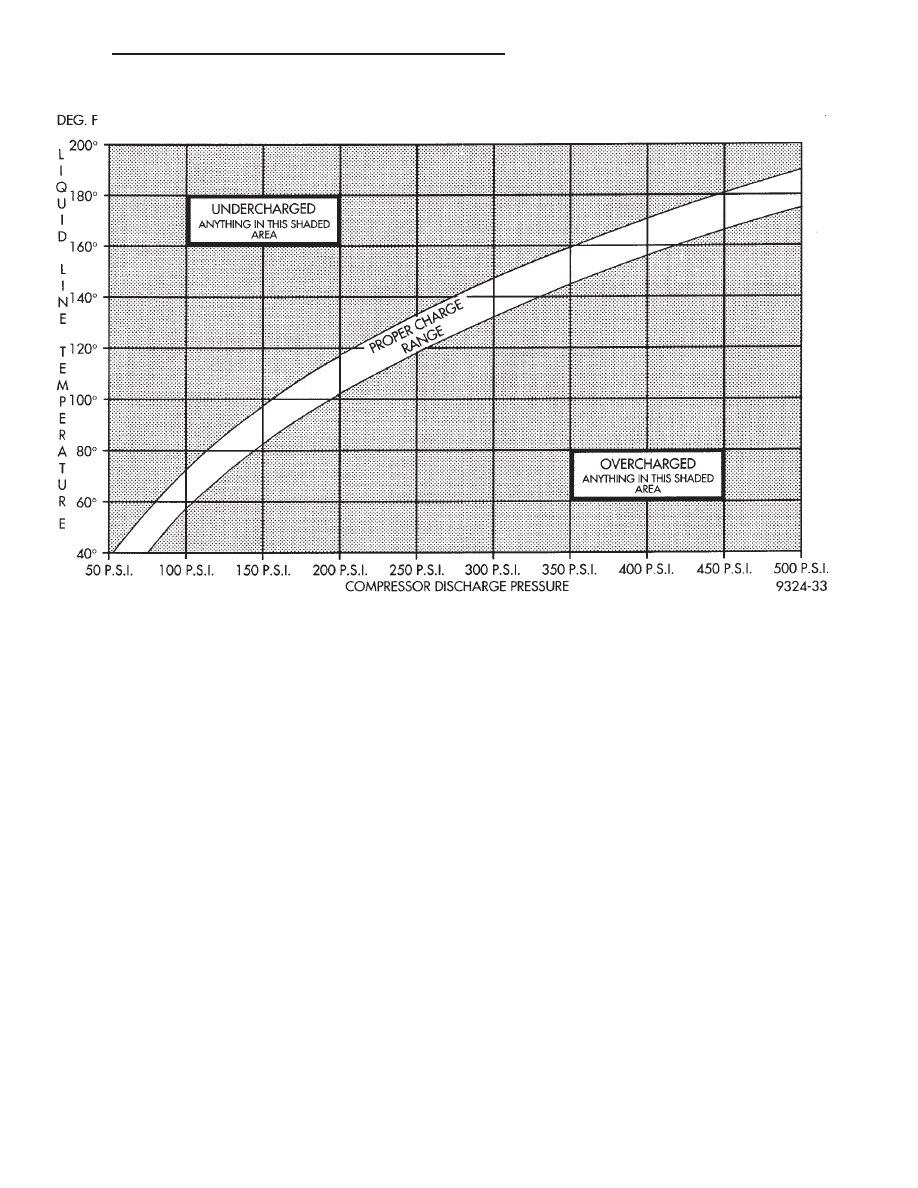
(1) Determine if there is any (R-134a) refrigerant

in the system. Use the scan tool (DRB) partial charge
test or pressure gauge liquid line temperature partial
charge check. See system charge level check or fill for
procedure.

(2) Position the vehicle in a wind free work area.

This will aid in detecting small leaks.

(3) Bring the refrigerant system up to operating

temperature and pressure. This is done by allowing
the engine to run for five minutes with the system
set to the following:

• Transaxle in Park

• Engine Idling

• A/C Controls Set in 100 percent outside air

• Blower switch in the high A/C position

• A/C in the ON position

• Open all windows

CAUTION: A leak detector designed for R-12 refrig-
erant may not detect leaks in a R-134a refrigerant
system. Check specifications on leak detector.

Fig. 12 Charge Determination Graph

300M

HEATING AND AIR CONDITIONING

24 - 15

SERVICE PROCEDURES (Continued)

(4) Shut off the vehicle and wait 2 to 7 minutes.

Then use an Electronic Leak Detector that is
designed to detect R-134a type refrigerant and search
for leaks. Fittings, lines, or components that appear
to be oily usually indicates a refrigerant leak. To
inspect the evaporator core for leaks, insert the leak
detector probe into the drain tube opening or a heat
duct.

If a thorough leak check has been completed with-

out indication of a leak, proceed to System Charge
Level.

NOTE: If leak is not detected but known to exist,
further diagnosis may be necessary using a refrig-
erant dye and the recovery machine. Refer to recov-
ery machine instructions for proper dye injection
procedures.

REMOVAL AND INSTALLATION

A/C PRESSURE TRANSDUCER

CAUTION: A/C pressure transducer switch connec-
tor terminal contacts can be damaged by probing
tools during system diagnosis and repair. Failure to
use their respective mating terminals or pin gauge
to check for tightness will cause contact beam
spreads. This will result in loss of continuity.

O-ring replacement is required whenever the pres-

sure transducer is serviced. Be sure to use the O-ring
specified for this vehicle.

The A/C pressure transducer is screwed on to a

valve on the discharge line. The transducer can be
removed or installed without evacuating the refriger-
ant from the A/C system.

NOTE: For 3.2/3.5L applications, the passenger
side headlamp must be rotated out of the way to
access the A/C pressure transducer.

REMOVAL

(1) Open hood and disconnect the negative battery

cable remote terminal from the remote battery post
(Fig. 13).

(2) Disconnect the wire harness connector from the

A/C pressure transducer.

CAUTION: A slight release of pressure trapped in
the fitting may be experienced. It is not necessary
to discharge the refrigerant system.

(3) Remove the transducer with a counterclockwise

rotation using a 14 mm open-end wrench.

INSTALLATION

For installation, reverse the above procedures.

Tighten pressure transducer to 6 N·m (50 in. lbs.).

AMBIENT TEMPERATURE SENSOR

The ambient air temperature sensor is located on

the inside of the right front bumper beam (Fig. 14).
This sensor will inform the ATC system of the ambi-
ent temperature outside the vehicle. This sensor is
used by the ATC system to adjust blower speed, tem-
perature offsets, evaporator temperatures and mode
control.

The ambient sensor is not serviceable and must be

replaced if found to be defective.

The ambient temperature sensor is used on all LH

vehicles with or without ATC systems.

To test Ambient Temperature Sensor, refer to

proper LH Body Diagnostic Manual.

REMOVAL

(1) Remove sensor mounting screw.
(2) Disconnect sensor wiring connector.

INSTALLATION

For installation, reverse the above procedures.

ATC IN-CAR TEMPERATURE SENSOR

The ATC In-Car Temperature Sensor is located in

the Control Head. The Control Head must be
removed for service to the sensor.

REMOVAL

(1) Open hood and disconnect the negative battery

cable remote terminal from the remote battery post
(Fig. 13).

Fig. 13 Negative Battery Cable Remote Terminal

24 - 16

HEATING AND AIR CONDITIONING

300M

SERVICE PROCEDURES (Continued)

(2) Remove snap-on center bezel which holds the

ATC Control.

(3) Disconnect the ATC Control from the vehicle

wiring harness.

(4) If the ATC in-car temperature sensor (fault 26)

is verified to be bad, then the ATC control section of
the assembly must be replaced. If the ATC in-car
sensor does not pass the paper test, then the problem
may only be with the ATC In-Car Sensor Fan-Motor
assembly.

(5) Remove the fan-motor assembly from the ATC

control with two screws located on the back of the
ATC control.

(6) Replace only the fan-motor assembly if control

does not pass the paper test, but passes with no fault
code 26 (bad thermistor).

NOTE: Retest control. If ATC control still fails the
paper test, then replace the ATC control and the
fan-motor assembly. The ATC Control must be
replaced if the part fails fault code 26 (after confirm-
ing proper wiring connections).

INSTALLATION

For installation, reverse the above procedures.

BLOWER MOTOR AND WHEEL ASSEMBLY

The blower motor is located on the right side of the

heater housing. The blower motor and the blower
motor wheel must be replaced as an assembly.

REMOVAL

(1) Open hood and disconnect the negative battery

cable remote terminal from the remote battery post
(Fig. 13).

(2) Remove lower right under panel duct.
(3) Remove blower motor connector from resistor

block/power module.

(4) Squeeze blower motor wiring grommet and

push grommet through blower motor housing cover.

(5) Remove blower motor housing cover.
(6) Remove blower motor retaining screws.
(7) Lower blower motor from housing.

INSTALLATION

For installation, reverse the above procedures.

BLOWER MOTOR POWER MODULE

REMOVAL

The Blower Motor Power Module is used on ATC

systems only.

(1) Open hood and disconnect the negative battery

cable remote terminal from the remote battery post
(Fig. 13).

(2) Remove lower right underpanel silencer/duct.
(3) Disconnect wiring connectors on blower motor

resistor.

(4) Remove blower motor resistor retaining screws.
(5) Pull blower motor resistor out of heater housing.

INSTALLATION

For installation, reverse the above procedures.

BLOWER MOTOR RESISTOR

REMOVAL

The Blower Motor Resistor is used on manual

Heater-A/C systems only.

(1) Open hood and disconnect the negative battery

cable remote terminal from the remote battery post
(Fig. 13).

(2) Remove lower right underpanel silencer/duct.
(3) Disconnect wiring connectors on blower motor

resistor.

(4) Remove blower motor resistor retaining screws.
(5) Pull blower motor resistor out of heater housing.

Fig. 14 Ambient Temperature Sensor Location

Fig. 15 ATC In-Car Temperature Sensor

300M

HEATING AND AIR CONDITIONING

24 - 17

REMOVAL AND INSTALLATION (Continued)

INSTALLATION

For installation, reverse the above procedures.

BLOWER MOTOR WHEEL

The blower motor wheel is only serviced with the

blower motor. The wheel and the motor are balanced
as an assembly. If the blower motor wheel requires
replacement, the blower motor must also be replaced.
Refer to blower motor for replacement procedure.

COMPRESSOR

The A/C compressor may be unbolted and reposi-

tioned without discharging the refrigerant system.
Discharging is not necessary if removing the com-
pressor clutch/coil assembly, engine, cylinder head, or
alternator.

WARNING: REFRIGERANT

PRESSURES

REMAIN

HIGH

EVEN

THOUGH

THE

ENGINE

MAY

BE

TURNED OFF. DO NOT TWIST OR KINK THE
REFRIGERANT LINES WHEN REMOVING A FULLY
CHARGED

COMPRESSOR.

SAFETY

GLASSES

MUST BE WORN.

REMOVAL

(1) Disconnect Negative battery cable.
(2) Loosen and remove drive belts (refer to Group

7, Engine Cooling) and disconnect compressor clutch
wire lead.

(3) Remove refrigerant from the A/C system (with

a refrigerant recovery machine) if the compressor is
being replaced.

(4) Remove refrigerant lines from compressor and

disconnect electrical connector.

(5) If system is left open place plug/cap over open

lines.

(6) Remove compressor attaching bolts.
(7) Remove compressor. If refrigerant lines were

not removed, lift compressor/clutch assembly and tie
it to a suitable component.

INSTALLATION

For installation, reverse the above procedures.

Torque Compressor bolts to 28 N·m (21 ft. lbs.)

COMPRESSOR HIGH-PRESSURE RELIEF VALVE

The high pressure relief valve is located on the A/C

compressor manifold (Fig. 16).

REMOVAL

(1) Remove refrigerant from A/C system using a

refrigerant recovery machine.

(2) Rotate the high pressure relief valve counter-

clockwise and separate relief valve from the vehicle.

INSTALLATION

For installation, reverse the above procedures

using a new O-ring seal. Evacuate and charge the
refrigerant system. Torque 5/8” Hex to 13.5 N·m (10
ft. lbs.).

COMPRESSOR CLUTCH/COIL ASSEMBLY

REMOVAL

Compressor assembly must be removed from mount-

ing. Although, refrigerant discharge is not necessary.

(1) Remove the compressor shaft bolt (Fig. 17). A

band type oil filter removal tool can be placed around
the clutch plate to aid in bolt removal.

(2) Tap the clutch plate with a plastic hammer and

remove clutch plate and shim(s) (Fig. 18).

CAUTION: Do not use screwdrivers between the
clutch plate assembly and pulley to remove front
plate as this may damage the front plate assembly.

(3) Remove pulley retaining snap ring with Snap

Ring Pliers (C-4574), and slide pulley assembly off of
compressor (Fig. 19).

(4) Remove coil wire bracket/ground clip screw and

wire harness.

(5) Remove snap ring retaining field coil onto com-

pressor housing (Fig. 20). Slide field coil off of com-
pressor housing.

(6) Examine frictional faces of the clutch pulley

and front plate for wear. The pulley and front plate
should be replaced if there is excessive wear or scor-
ing. If the friction surfaces are oily, inspect the shaft
nose area of the compressor for oil and remove the
felt from the front cover. If the compressor felt is sat-
urated with oil, the shaft seal is leaking and will
have to be replaced.

(7) Check bearing for roughness or excessive leak-

age of grease. Replace bearing as required.

Fig. 16 High Pressure Relief Valve

24 - 18

HEATING AND AIR CONDITIONING

300M

REMOVAL AND INSTALLATION (Continued)


Content   ..  332  333  334  335   ..