Chrysler New Yorker. Manual - part 321


  Index      Chrysler     Chrysler New Yorker - service repair manual 1997-1999 year


Search            


Content   ..  319  320  321  322   ..


Chrysler New Yorker. Manual - part 321


FRONT SEAT BACK

REMOVAL

(1) Remove seat from vehicle.
(2) Remove seat cushion side shields.
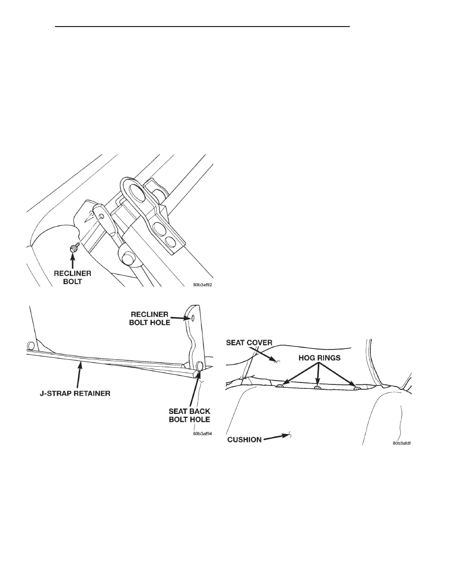
(3) Remove bolts attaching recliner to seat back

cushion frame (Fig. 46).

(4) Remove inboard pivot bolt (Fig. 47).
(5) Connect any electrical connectors to the seat

back, if equipped.

(6) Separate seat back from seat cushion.

INSTALLATION

(1) Position seat back on cushion.
(2) Connect electrical connectors to the seat back,

if equipped.

(3) Install inboard pivot bolt. Tighten bolt to 30

N·m (22 ft. lbs.) torque.

(4) Install bolts attaching recliner to seat cushion

frame. Tighten bolts to 14 N·m (10 ft. lbs.) torque.

(5) Install seat cushion side shields.
(6) Install seat in vehicle.

FRONT SEAT BACK COVER

REMOVAL

(1) Remove seat from vehicle.
(2) Remove head rest.
(3) Remove front seat back.
(4) Remove lumbar support handle, if equipped.
(5) Disengage the J-strap retainer (Fig. 47).
(6) Roll cover upward to hog rings. Cut hog rings

to free cover (Fig. 48).

(7) Roll cover to top of cushion and remove head

rest sleeve guides.

(8) Remove cover from seat back.

INSTALLATION

NOTE: Do not reuse the recliner assembly attach-
ing bolts.

(1) Position cover at the top of seat back.
(2) Carefully roll cover down to the area that hog

rings are to be installed.

(3) Install hog rings.
(4) Roll cover downward.
(5) Engage the J-strap retainer.
(6) Install lumbar support handle, if equipped.
(7) Install new head rest sleeve guides.
(8) Install seat back to seat cushion. Tighten bolts

to 30 N·m (22 ft. lbs.) torque.

(9) Install seat in vehicle.
(10) Install head rest.
(11) Check seat back operation.

FRONT SEAT BELT RETRACTOR

Inspect the condition of the shoulder belt and lap

belt. Replace any belt that is cut, frayed, torn, or
damaged in any way. Also, replace the shoulder belt
if the retractor is either damaged or inoperative.

REMOVAL

(1) If necessary, move the front seat(s) all the way

forward for access.

Fig. 46 Recliner Attaching Bolt

Fig. 47 Remove Seat Back

Fig. 48 Front Seat Back Hog Rings

300M

BODY

23 - 25

REMOVAL AND INSTALLATION (Continued)

(2) Detach the turning loop cover from the upper

anchor bolt.

(3) Remove upper anchor bolt (Fig. 49).
(4) Remove B-pillar upper trim.
(5) Remove lower anchor bolt.
(6) Remove the retractor anchor bolt.
(7) Disconnect retractor wire harness connector.
(8) Remove retractor from vehicle.

INSTALLATION

(1) Position the retractor in the vehicle.
(2) Install the retractor anchor bolt. Tighten to 60

N·m (44 ft. lbs.) torque.

(3) Connect retractor wire harness connector.
(4) Install the lower anchor bolt. Tighten to 60

N·m (44 ft. lbs.) torque.

(5) Route the belt webbing through the access slots

in B-pillar upper trim.

(6) Install B-pillar upper trim.
(7) Install the upper anchor bolt. Tighten to 60

N·m (44 ft. lbs.) torque.

(8) Close turning loop covers.

FRONT SEAT CENTER OCCUPIED BELT BUCKLE –
CONCORDE/INTREPID

REMOVAL

(1) Move or remove front seat as necessary to gain

access to seat belt buckle anchor bolt.

(2) Remove bolt attaching buckle and reinforce-

ment to front seat track (Fig. 50).

(3) Remove seat belt buckle from vehicle.

INSTALLATION

(1) Place seat belt buckle in position on vehicle.
(2) Install bolt attaching buckle and reinforcement

to front seat track or floor. Tighten bolt to 60 N·m (44
ft. lbs.) torque.

(3) Install front seat, if it was removed.

FRONT SEAT CUSHION

REMOVAL

(1) Remove seat from vehicle.
(2) Remove front seat cushion side shields and dis-

connect wire connectors, if equipped.

(3) Remove seat back.
(4) Remove track and recliner assembly.
(5) Disconnect seat cushion heater element connec-

tor, if equipped.

(6) Disconnect wire harness fasteners from cushion

frame (Fig. 51).

(7) Remove seat cushion (Fig. 52).

INSTALLATION

(1) Install

wire

harness

fasteners

to

cushion

frame.

(2) Connect seat cushion heater element connector,

if equipped.

(3) Install track and recliner assembly.
(4) Install seat back. Tighten bolts to 30 N·m (22

ft. lbs.) torque.

(5) Connect switch wire connectors to the cushion

side shield, if equipped.

(6) Install cushion side shields.
(7) Install seat in vehicle.

Fig. 50 Front Seat Center Occupied Belt Buckle –

Typical

Fig. 49 Front Shoulder Belt Adjuster

23 - 26

BODY

300M

REMOVAL AND INSTALLATION (Continued)

FRONT SEAT CUSHION COVER

REMOVAL

(1) Remove seat from vehicle.
(2) Remove front seat cushion side shields.
(3) Remove seat back.
(4) Remove track and reclined assembly.
(5) Disengage J-strap attaching seat cover from

the seat cushion frame(Fig. 53).

(6) Pull cover off to the hog rings (Fig. 54).
(7) Cut hog rings attaching seat cover seat cush-

ion.

(8) Route seat function switches through access

hole on outboard side of seat cushion, if equipped.

(9) Disconnect seat cushion heater element connec-

tor, if equipped.

(10) Separate seat cushion cover from seat cush-

ion.

INSTALLATION

(1) Position seat cover on cushion.
(2) Align seat cover with cushion alignment inden-

tations.

(3) Engage seat cushion heater element connector,

if equipped.

(4) Install hog rings.
(5) Engage J-strap attaching seat cover to front of

seat cushion frame.

(6) Install track and recliner assembly.
(7) Install seat back.
(8) Install front seat cushion side shields.
(9) Install seat in vehicle.

FRONT SEAT CUSHION SIDE SHIELD

REMOVAL

(1) Remove seat from vehicle.
(2) Remove screws attaching seat cushion side

shield to the bottom and side of seat cushion (Fig. 56)
and (Fig. 57).

(3) Remove shield from seat.
(4) Disconnect switch wire connectors, if equipped.
(5) Remove seat switches, if equipped.

INSTALLATION

(1) Transfer seat switches, if equipped.
(2) Connect switch wire connectors to cushion side

shield, if equipped.

Fig. 51 Front Seat Cushion Wire Harness

Fig. 52 Front Seat Cushion

Fig. 53 Front Seat Cushion J- Strap

Fig. 54 Seat Cushion Cover

300M

BODY

23 - 27

REMOVAL AND INSTALLATION (Continued)

(3) Place shield in position on seat cushion.
(4) Install screws attaching seat cushion side

shield.

(5) Install seat. Tighten front screws to 60 N·m (44

ft. lbs.), and the rear screws to 48 N·m (35 ft. lbs.).

FRONT SEAT HEAD REST

REMOVAL

(1) Lower head rest slightly.
(2) Insert a stiff wire into the hole on the right

hand side head rest sleeve/guide and push to release
latch (Fig. 58).

(3) At the same time, press the button on the head

rest sleeve/guide left hand side and pull upward to
release the head rest.

(4) Remove head rest from seat back.

INSTALLATION

(1) Place head rest in position.
(2) Push head rest down into the lock position.
(3) Raise head rest to ensure it locks at the last

stop.

FRONT SEAT LUMBAR SUPPORT

The front seat lumbar support is not service sepa-

rately. The front seat back frame will need to be
replaced.

FRONT SEAT TRACK AND RECLINER

REMOVAL

(1) Remove front seat from vehicle.
(2) Remove seat cushion side shield and disconnect

switch connector, if equipped.

(3) Remove bolt attaching seat back recliner to

seat back frame on each side of seat (Fig. 59).

(4) Remove bolts attaching seat track and recliner

to cushion frame (Fig. 60).

(5) Remove seat track and recliner from seat cush-

ion.

INSTALLATION

(1) Place seat track in position on seat cushion.
(2) Install bolts to attach seat track and recliner to

cushion frame.

(3) Install bolt to attach seat back recliner to seat

back on each side of seat. Tighten bolt to 30 N·m (22
ft. lbs.) torque.

(4) Connect wire connectors and install the cush-

ion side shields.

(5) Install front seat in vehicle.

Fig. 55 Seat Cushion Alignment Indentations

Fig. 56 Bottom View of Side Shield

Fig. 57 Side View of Side Shield

Fig. 58 Head Rest Removal

23 - 28

BODY

300M

REMOVAL AND INSTALLATION (Continued)


Content   ..  319  320  321  322   ..