Chrysler New Yorker. Manual - part 258


  Index      Chrysler     Chrysler New Yorker - service repair manual 1997-1999 year


Search            


Content   ..  256  257  258  259   ..


Chrysler New Yorker. Manual - part 258


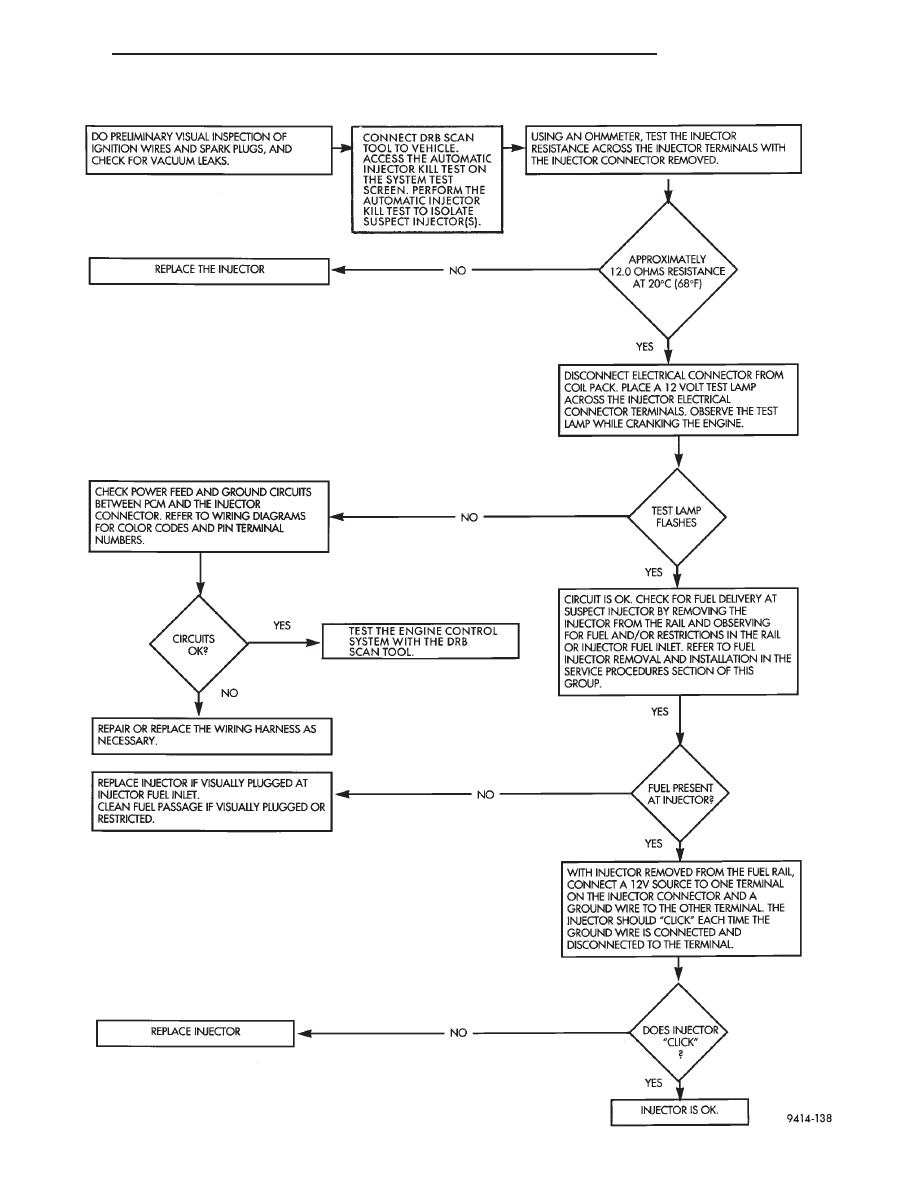
FUEL INJECTOR DIAGNOSIS

300M

FUEL SYSTEM

14 - 7

DIAGNOSIS AND TESTING (Continued)

SERVICE PROCEDURES

FUEL SYSTEM PRESSURE RELEASE PROCEDURE

(1) Remove Fuel Pump relay from Power Distribu-

tion Center (PDC). For location of relay, refer to label
on underside of PDC cover.

(2) Start and run engine until it stalls.
(3) Attempt restarting engine until it will no

longer run.

(4) Turn ignition key to OFF position.

CAUTION: Steps 1, 2, 3 and 4 must be performed to
relieve high pressure fuel from within fuel rail. Do
not attempt to use following steps to relieve this
pressure as excessive fuel will be forced into a cyl-
inder chamber.

(5) Unplug connector from any injector.
(6) Attach one end of a jumper wire with alligator

clips (18 gauge or smaller) to either injector terminal.

(7) Connect other end of jumper wire to positive

side of battery.

(8) Connect one end of a second jumper wire to

remaining injector terminal.

CAUTION: Powering an injector for more than a few
seconds will permanently damage the injector.

(9) Momentarily touch other end of jumper wire to

negative terminal of battery for no more than a few
seconds.

(10) Place a rag or towel below fuel line quick-con-

nect fitting at fuel rail.

(11) Disconnect quick-connect fitting at fuel rail.

Refer to Quick-Connect Fittings in this section.

(12) Return fuel pump relay to PDC.
(13) One or more Diagnostic Trouble Codes (DTC’s)

may have been stored in PCM memory due to fuel
pump relay removal. The DRB scan tool must be
used to erase a DTC. Refer to Group 25, Emission
Control System. See On-Board Diagnostics.

DRAINING FUEL TANK

Raise and support vehicle on hoist. Obtain the

proper container for GASOLINE. Remove drain plug
and drain fuel tank (Fig. 7).

HOSES AND CLAMPS

Inspect all hose connections (clamps and quick con-

nect fittings) for completeness and leaks. Replace
cracked, scuffed, or swelled hoses. Replace hoses that
rub against other vehicle components or show sign of
wear.

Fuel injected vehicles use specially constructed

hoses. When replacing hoses, only use hoses marked
EFM/EFI.

When installing hoses, ensure that they are routed

away from contact with other vehicle components
that could rub against them and cause failure. Avoid
contact with clamps or other components that cause
abrasions or scuffing. Ensure that rubber hoses are
properly routed and avoid heat sources.

The hose clamps have rolled edges to prevent the

clamp from cutting into the hose. Only use clamps
that are original equipment or equivalent. Other
types of clamps may cut into the hoses and cause
high pressure fuel leaks. Tighten hose clamps to 1
N·m (10 in. lbs.) torque.

QUICK-CONNECT FITTINGS

REMOVAL

When disconnecting a quick-connect fitting, the

retainer will remain on the fuel tube nipple.

WARNING:

RELEASE FUEL SYSTEM PRESSURE

BEFORE DISCONNECTING A QUICK-CONNECT FIT-
TINGS. REFER TO THE FUEL PRESSURE RELEASE
PROCEDURE.

(1) Disconnect negative cable from battery.
(2) Perform

Fuel

Pressure

Release

Procedure.

Refer to the Fuel Pressure Release Procedure in this
section.

(3) Squeeze retainer tabs together and pull fuel

tube/quick-connect fitting assembly off of fuel tube
nipple. The retainer will remain on fuel tube.

Fig. 7 Fuel Tank Drain Plug

14 - 8

FUEL SYSTEM

300M

INSTALLATION

CAUTION:

Never install a quick-connect fitting

without the retainer being either on the fuel tube or
already in the quick-connect fitting. In either case,
ensure the retainer locks securely into the quick-
connect fitting by firmly pulling on fuel tube and fit-
ting to ensure it is secured.

(1) Using a clean lint free cloth, clean the fuel tube

nipple and retainer.

(2) Prior to connecting the fitting to the fuel tube,

coat the fuel tube nipple with clean 30 weight engine
oil.

(3) Push the quick-connect fitting over the fuel

tube until the retainer seats and a click is heard.

(4) The plastic quick-connect fitting has windows

in the sides of the casing. When the fitting com-
pletely attaches to the fuel tube, the retainer locking
ears and the fuel tube shoulder are visible in the
windows. If they are not visible, the retainer was not
properly installed (Fig. 8). Do not rely upon the
audible click to confirm a secure connection.

CAUTION:

When using the ASD Fuel System Test,

the Auto Shutdown (ASD) Relay remains energized
for either 7 minutes, until the test is stopped, or
until the ignition switch is turned to the Off posi-
tion.

(5) Use the DRB scan tool ASD Fuel System Test

to pressurize the fuel system. Check for leaks.

REMOVAL AND INSTALLATION

AUTOMATIC SHUTDOWN RELAY

The relay is located in the Power Distribution Cen-

ter (PDC) (Fig. 9). For the location of the relay
within the PDC, refer to the PDC cover for location.
Check electrical terminals for corrosion and repair as
necessary.

FUEL PUMP RELAY

The fuel pump relay is located in the PDC. The

inside top of the PDC cover has a label showing relay
and fuse location.

FUEL PUMP MODULE

REMOVAL

(1) Release fuel pressure, Refer to Fuel System

Pressure Release Procedure in Group 14, Fuel Deliv-
ery.

(2) Remove Fuel Tank refer to the Fuel Tank

Removal/Installation in this group.

WARNING:

THE FUEL RESERVOIR OF THE FUEL

PUMP MODULE DOES NOT EMPTY OUT WHEN THE
TANK IS DRAINED. THE FUEL IN THE RESERVOIR
WILL

SPILL

OUT

WHEN

THE

MODULE

IS

REMOVED.

(3) Disconnect fuel line from fuel pump module by

depressing quick connect retainers with thumb and
fore finger.

(4) Slide fuel pump module electrical connector

lock to unlock.

(5) Disconnect the electrical connection from the

fuel pump module, by pushing down on connector
retainer and pulling connector off of module.

(6) Use Special Tool 6856 to remove fuel pump

module locknut (Fig. 10).

(7) Remove fuel pump and O-ring seal from tank.

Discard old seal.

INSTALLATION

(1) Wipe seal area of tank clean and place a new

seal in position in the tank opening.

Fig. 8 Plastic Quick-Connect Fitting/Fuel Tube

Connection

Fig. 9 Power Distribution Center (PDC)

300M

FUEL SYSTEM

14 - 9

SERVICE PROCEDURES (Continued)

(2) Position fuel pump in the tank. Make sure the

alignment tab on the underside of the fuel pump
module flange sits in the notch on the fuel tank (Fig.
11).

(3) Position the locknut over the fuel pump mod-

ule.

(4) Tighten the locknut using Special Tool 6856 to

55 N·m (40.5 ft. lbs.).

CAUTION: Over tightening the pump lock ring may
result in a leak.

(5) Raise the fuel tank on the transmission stand.
(6) Install fuel pump electrical connector into hole

in the body.

(7) Connect the purge and vent lines.

(8) Raise tank into position and install tank

straps.

(9) Install the fuel filler tube and tighten the

clamp.

(10) Reposition the stabilizer bar and install bolts.
(11) Lower vehicle.
(12) Connect the fuel pump electrical connector

that is in the rear seat.

(13) Install the rear seat.
(14) Connect the battery cable.
(15) Fill fuel tank. Use the DRB scan tool to pres-

surize the fuel system. Check for leaks.

FUEL PRESSURE/REGULATOR

REMOVAL

(1) Release fuel pressure, Refer to Fuel System

Pressure Release Procedure in Group 14, Fuel Deliv-
ery.

(2) Remove Fuel Tank refer to the Fuel Tank

Removal/Installation in this group.

(3) Lower fuel tank and remove the purge line and

vent line.

(4) Disconnect fuel line from pressure regulator.
(5) Push locking tab in from locking slot. Turn

pressure regulator to unlock it (Fig. 12).

(6) Pull regulator straight up.

INSTALLATION

(1) Push regulator down and into place.
(2) Turn fuel pressure regulator to lock it in place

(Fig. 12). Make sure take the locking tab is in the
locking slot.

(3) Connect fuel line to regulator
(4) Raise the fuel tank on the transmission stand.
(5) Install fuel pump electrical connector into hole

in the body.

(6) Connect the purge and vent lines.

Fig. 10 Fuel Tank Locknut

Fig. 11 Fuel Tank Locator Notch

Fig. 12 Fuel Pressure Regulator Locking Tab

14 - 10

FUEL SYSTEM

300M

REMOVAL AND INSTALLATION (Continued)


Content   ..  256  257  258  259   ..