Chrysler New Yorker. Manual - part 223


  Index      Chrysler     Chrysler New Yorker - service repair manual 1997-1999 year


Search            


Content   ..  221  222  223  224   ..


Chrysler New Yorker. Manual - part 223


(4) Remove Intake Manifold. Refer to Group 11,

Exhaust System and Intake Manifold for removal
procedure.

(5) Remove cylinder head covers and spark plugs.

Refer to this section for procedure.

(6) Remove rocker arm and shaft assembly. Refer

to this section for procedure.

(7) Rotate the crankshaft clockwise, until the num-

ber 1 piston is at TDC (Top Dead Center) on the com-
pression stroke.

(8) With air hose attached to spark plug adapter

installed in number 1 spark plug hole, apply 620.5 to
689 kPa (90 to 100 psi) air pressure. This is to hold
valves into place while servicing components.

(9) Using Tool MD 998772A with adapter 6527 or

equivalent, compress valve spring and remove valve
locks, retainer, and valve spring.

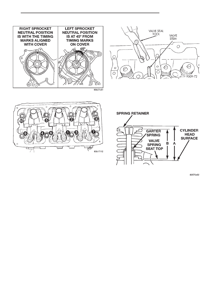
(10) Remove valve stem seals by using a valve

stem seal tool (Fig. 60).

(11) The valve stem seal/valve spring seat should

be pushed firmly and squarely over the valve guide
using the valve stem as guide. Do Not Force seal
against top of guide. When installing the valve

retainer locks, compress the spring only enough to
install the locks.

CAUTION: Do not remove garter spring around the
seal at the top of the valve stem seal (Fig. 61).

(12) Follow the same procedure on the remaining 5

cylinders using the firing sequence 1-2-3-4-5-6. Make
sure piston in cylinder is at TDC on the valve
spring that is being covered.

(13) Remove spark plug adapter tool.
(14) Remove Special Tool MD 998772A and install

rocker arm assembly. Refer to procedure outlined in
this section.

(15) Install cylinder head covers. Refer to proce-

dure outline in this section.

(16) Install ignition coils and connect all electrical

connectors.

(17) Install intake manifold plenum. Refer to

Group 11, Exhaust System and Intake Manifold.

(18) Connect negative cable.

Fig. 58 Camshaft Sprockets Neutral Position

Fig. 59 Rocker Arm and Shaft Assembly Tightening

Sequence

Fig. 60 Valve Stem Seal—Removal

Fig. 61 Valve Seal Garter Spring

LH

3.2L ENGINE

9 - 87

REMOVAL AND INSTALLATION (Continued)

VALVE AND VALVE SPRINGS

REMOVAL

(1) With cylinder head removed, compress valve

springs using the Valve Spring Compressors shown
in (Fig. 62).

(2) Remove valve retaining locks, valve spring

retainers, valve springs and valve spring seat/stem
seal assembly.

(3) Before removing valves, remove any burrs

from valve stem lock grooves to prevent dam-
age to the valve guides. 
Identify valves to insure
installation in original location.

INSTALLATION

(1) Coat valve stems with clean engine oil and

insert them in cylinder head.

(2) If valves or seats have been reground, check

valve tip height (A) (Fig. 63). If valve tip height is
greater than 43.65 mm (1.7185 in.) intake or 45.98
mm (1.8102 in.) exhaust, grind valve tip until within
specifications. Make sure measurement is taken from
cylinder head surface to the top of valve stem.

(3) Install valve seal/spring seat assembly over

valve guides on all valve stems (Fig. 64). Ensure that
the garter spring is intact around the top of the rub-
ber seal. Install valve springs, valve retainers.

(4) Compress valve springs with a valve spring

compressor install locks and release tool. If valves
and/or

seats

are

reground,

measure

the

installed height of springs (B) (Fig. 63), make
sure measurements are taken from top of
spring seat to the bottom surface of spring
retainer
. If height is greater than 38.75 mm (1.5256
inches), install a .762 mm (0.030 inch.) spacer in
head counterbore under the valve spring seat to
bring spring height back within specification.

TIMING BELT COVERS

REMOVAL

(1) Disconnect negative cable from remote jumper

terminal.

(2) Remove upper radiator crossmember. Refer to

Group 23, Body for procedure.

(3) Remove fan module. Refer to Group 07, Cooling

System for procedure.

(4) Remove the accessory drive belts. Refer to

Group 07, Accessory Drive System for service proce-
dure.

(5) Use Special Tool 8191 to hold crankshaft

damper while removing center bolt.

(6) Remove crankshaft damper using Special Tools

1023 and C-4685-C2 (Fig. 65).

Fig. 62 Valve Spring Compressors

Fig. 63 Checking Valve Tip Height and Valve Spring

Installed Height

Fig. 64 Valve, Spring, and Valve Seal—Installation

9 - 88

3.2L ENGINE

LH

REMOVAL AND INSTALLATION (Continued)

(7) Remove the lower belt cover located behind the

crankshaft damper (Fig. 66).

(8) Remove the stamped steel cover (Fig. 66). Do

not remove the sealer on the cover, it is reus-
able (Fig. 67). 
If some sealer is missing use Mopar

t

Silicone Rubber Adhesive Sealant or equivalent to
replace the missing sealer.

(9) Remove the left cast cover (Fig. 66).

INSTALLATION

(1) Install the left cast cover and accessory belt

tensioner pulley and bracket.

(2) Install the right stamped steel cover.
(3) Install the lower cover.
(4) Install the crankshaft damper using Special

Tools C-4685-C1 Bolt (5.9 in.) and 6792-1. Install cen-
ter bolt, and while holding damper with Special Tool
8191, tighten center bolt to 115 N·m (85 ft. lbs.).

(5) Install the fan module and upper radiator

crossmember.

(6) Connect negative cable to remote jumper termi-

nal.

TIMING BELT

REMOVAL

CAUTION: The following procedure can only be
used when the camshaft sprockets HAVE NOT
BEEN LOOSENED or removed from the camshafts.
Refer to Camshaft Sprocket and Engine Timing in
this Section, if sprocket(s) or camshaft(s) have
been loosened or removed.

CAUTION: The 3.2L is NOT a free–wheeling engine.
Care should be taken not to rotate the camshafts or
crankshaft with the timing belt removed.

(1) Disconnect negative cable from remote jumper

terminal.

(2) Remove upper radiator crossmember. Refer to

Group 23, body for procedure.

(3) Disconnect fan module electrical connector.
(4) Remove fan module. Refer to Group 07, Cooling

System for procedure.

(5) Remove accessory drive and air conditioning

drive belts. Refer to Group 07, Cooling System for
procedure.

(6) Remove crankshaft damper and front timing

belt covers. Refer to procedure outlined in this sec-
tion.

(7) Mark belt running direction, if timing belt is to

be reused.

CAUTION: When aligning timing marks, always
rotate engine by turning the crankshaft. Failure to
do so will result in valve and/or piston damage.

Fig. 65 Crankshaft Damper—Removal

Fig. 66 Timing Belt Covers

Fig. 67 Sealer, Timing Belt Cover

LH

3.2L ENGINE

9 - 89

REMOVAL AND INSTALLATION (Continued)

(8) Rotate engine clockwise until crankshaft mark

aligns with the TDC mark on oil pump housing and
the camshaft sprocket timing marks are between the
marks on the rear covers (Fig. 68).

CAUTION: Align the camshaft sprockets between
the marks on rear belt covers before timing belt
removal or damage to valve and/or pistons could
occur.

(9) Using a ink or paint marker; mark the exact

position of the camshaft sprocket timing mark rela-
tive to the two timing marks on the rear timing
cover.

NOTE: When timing belt tensioner is removed from
engine, always store in the vertical (plunger facing
upward) position.

(10) Remove the timing belt tensioner (Fig. 69)

and remove timing belt.

TIMING BELT TENSIONER
(11) When tensioner is removed from the engine it

is necessary to compress the plunger into the ten-
sioner body.

CAUTION: Compress the tensioner slowly, as dam-
age to tensioner could result.

(12) Place the tensioner into a vise and SLOWLY

compress the plunger (Fig. 70). Total bleed down of
tensioner should take about 5 minutes.

CAUTION: Index the tensioner in the vise the same
way it is installed on the engine. This is to ensure
proper pin orientation when tensioner is installed
on the engine.

(13) When plunger is compressed into the ten-

sioner body install a pin through the body and

plunger to retain plunger in place until tensioner is
installed.

NOTE: When the tensioner is removed from the
engine, always store with the plunger pointing
upward.

INSTALLATION

CAUTION:

This procedure can only be used when

the camshaft sprockets HAVE NOT BEEN LOOS-
ENED or removed from the camshafts.

CAUTION: If camshafts have moved from the tim-
ing marks, always rotate camshaft towards the
direction nearest to the timing marks (DO NOT
TURN CAMSHAFTS A FULL REVOLUTION OR DAM-
AGE to valves and/or pistons could result).

Fig. 68 Engine Timing Mark Alignment

Fig. 69 Timing Belt System

Fig. 70 Compressing Timing Belt Tensioner

9 - 90

3.2L ENGINE

LH

REMOVAL AND INSTALLATION (Continued)


Content   ..  221  222  223  224   ..