Chrysler New Yorker. Manual - part 211


  Index      Chrysler     Chrysler New Yorker - service repair manual 1997-1999 year


Search            


Content   ..  209  210  211  212   ..


Chrysler New Yorker. Manual - part 211


(2) If front crankshaft seal was bench installed,

place Special Tool 6780-2, Sleeve over crankshaft
nose to guide and protect seal lip.

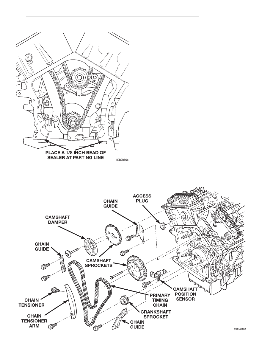
(3) Before installing timing cover gasket apply a

1/8 inch bead of Mopar

t Silicone Rubber Adhesive

Sealant to the parting lines between the oil pan and
cylinder block (Fig. 52).

(4) Install timing cover and gasket. Tighten M10

cover bolts to 54 N·m (40 ft. lbs.) and M6 bolts to 12
N·m (105 in. lbs.) (Fig. 51).

(5) If not previously performed, install crankshaft

oil seal using Special Tool 6780-2 sleeve and 6780-2
installer.

(6) Install crankshaft damper and tighten center

bolt to 170 N·m (125 ft. lbs.)

(7) Attach power steering pump to bracket.
(8) Install A/C belt tensioner assembly to timing

cover.

(9) Install accessory drive belt tensioner pulley

and bracket.

(10) Install fan module, A/C and accessory drive

belts. Refer to Group 07, Cooling System for procedure.

(11) Install upper radiator crossmember.
(12) Connect negative cable at right strut tower.

TIMING CHAIN AND SPROCKETS

Fig. 53 Primary Timing Drive System

Fig. 52 Timing Chain Cover Sealing

LH

2.7L ENGINE

9 - 39

REMOVAL AND INSTALLATION (Continued)

REMOVAL

(1) Remove upper intake manifold plenum. Refer

to Group 11, Exhaust System and Intake Manifold.

(2) Remove

cylinder

head

covers,

crankshaft

damper, and timing chain cover. Refer to procedures
outlined in this section.

CAUTION: When

aligning timing marks, always

rotate engine by turning the crankshaft. Failure to
do so will result in valve and/or piston damage.

(3) Align crankshaft sprocket timing mark to mark

on oil pump housing (Fig. 54). The mark on oil pump
housing is 60° ATDC of #1 cylinder.

CAUTION: When the timing chain is removed and
the cylinder heads are still installed, DO NOT rotate
the camshafts or crankshaft without first locating
the proper crankshaft position. Failure to do so will
result in valve and/or piston damage.

(4) Remove the primary timing chain tensioner

from right cylinder head (Fig. 53).

(5) Remove camshaft position sensor from left cyl-

inder head (Fig. 53).

(6) Remove chain guide access plug from left cylin-

der head (Fig. 53).

NOTE: When camshaft sprocket bolts are removed,
the camshafts will rotate in a clockwise direction.

(7) Starting with the right camshaft sprocket,

remove the sprocket attaching bolts. Remove cam-
shaft damper and sprocket (Fig. 53).

(8) Remove left side camshaft sprocket attaching

bolts and remove sprocket (Fig. 53).

(9) Remove lower chain guide and tensioner arm

(Fig. 53).

(10) Remove the primary timing chain.
(11) Inspect

all

sprockets

and

chain

guides.

Replace if worn. Refer to crankshaft sprocket, for
removal and installation procedures.

Fig. 54 Timing Mark Alignment

9 - 40

2.7L ENGINE

LH

REMOVAL AND INSTALLATION (Continued)

Fig. 55 Primary Timing Chain Marks

LH

2.7L ENGINE

9 - 41

REMOVAL AND INSTALLATION (Continued)

INSTALLATION

(1) Align crankshaft sprocket timing mark to the

mark on oil pump housing (Fig. 55).

NOTE: Lubricate timing chain and guides with
engine oil before installation.

(2) Place left side primary chain sprocket onto the

chain so that the timing mark is located in-between
the two plated links on chain (Fig. 55).

(3) Lower the primary chain with left side sprocket

through the left cylinder head opening.

NOTE: The camshaft sprockets can be allowed to
float on the camshaft hub during installation.

(4)

Loosely position left side camshaft sprocket

over camshaft hub.

(5) Align plated link to the crankshaft sprocket

timing mark (Fig. 55).

(6) Position primary chain onto water pump drive

sprocket.

(7) Align right camshaft sprocket timing mark to

plated link on timing chain (Fig. 55) and loosely posi-
tion over camshaft hub.

(8) Verify that all plated links are properly aligned

to timing marks on all sprockets (Fig. 55).

(9) Install left lower chain guide and tensioner

arm (Fig. 53). Tighten attaching bolts to 28 N·m (250
in. lbs.).

NOTE: Inspect oil ring on chain guide access plug
before installing. Replace O-ring as necessary.

(10) Install chain guide access plug to left cylinder

head (Fig. 53). Tighten plug to 20 N·m (15 ft. lbs.).

Fig. 56 Timing Chain Tensioner Assembly

Fig. 57 Timing Chain Tensioner—Oil Purging

Fig. 58 Timing Chain Tensioner Resetting

9 - 42

2.7L ENGINE

LH

REMOVAL AND INSTALLATION (Continued)


Content   ..  209  210  211  212   ..