Chrysler New Yorker. Manual - part 208


  Index      Chrysler     Chrysler New Yorker - service repair manual 1997-1999 year


Search            


Content   ..  206  207  208  209   ..


Chrysler New Yorker. Manual - part 208


(1) Remove cylinder head covers. Refer to proce-

dures outlined in this section.

(2) Rotate engine until number one cylinder is at

TDC on the EXHAUST stroke.

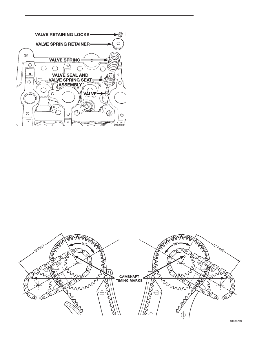
(3) View the intake camshaft sprocket timing

mark. The mark should be 90° from the cylinder
head cover sealing surface (Fig. 23) on both right and
left cylinder banks.

(4) Count chain pins from the mark on the intake

camshaft towards the exhaust camshaft. Engine is
timed correctly when there are 12 chain pins
between the timing marks on the intake camshaft
and exhaust camshaft (Fig. 23).

(5) If marks are not correctly aligned, proceed to

Camshafts, Timing Chain and Sprockets, Removal
and Installation procedures.

REMOVAL AND INSTALLATION

ENGINE MOUNTS—LEFT AND RIGHT

REMOVAL

(1) Raise vehicle on hoist.
(2) Remove the isolator attaching nuts from top of

the mounting bracket (Fig. 24).

(3) Support the engine with a jack and a block of

wood across the full width of the oil pan.

(4) Remove the lower attaching nuts from the bot-

tom of the isolator to the frame (Fig. 24).

(5) Raise engine carefully with jack enough to

remove the isolator with heat shield from its mount.

INSTALLATION

(1) Install isolator mount with heat shield onto the

frame.

(2) Lower the engine onto the isolator mount.
(3) Remove jack from vehicle.
(4) Tighten the isolator to frame nuts to 61 N·m

(45 ft. lbs.) (Fig. 24).

(5) Install the upper attaching nuts to mount and

tighten to 61 N·m (45 ft. lbs.) (Fig. 24).

(6) Lower vehicle.

ENGINE HYDRO-MOUNT ISOLATORS

Engine hydro-mounts may show surface cracks,

this will not effect performance and hydro-mount
should not be replaced. Only replace the engine
hydro-mounts when leaking fluid:

• Driveshaft distress: Refer to Driveshafts in Sus-

pension, Group 2.

• Any front end structural damage (after repair).

• Isolator replacement.

Fig. 22 Valve Seal and Spring

Fig. 23 Engine Timing

LH

2.7L ENGINE

9 - 27

SERVICE PROCEDURES (Continued)

ENGINE MOUNT—REAR

REMOVAL

(1) Raise vehicle on hoist.
(2) Support transaxle with a jack.
(3) Remove isolator nuts from the mount to tran-

saxle mount bracket (Fig. 24).

(4) Remove rear mount isolator bolts to crossmem-

ber and remove mount (Fig. 24).

INSTALLATION

(1) Position isolator onto crossmember.
(2) Install bolts attaching isolator to crossmember

and tighten to 33 N·m (250 in. lbs.) (Fig. 24).

(3) Lower transaxle onto isolator
(4) Install isolator nuts and tighten to 61 N·m (45

ft. lbs.) (Fig. 24).

(5) Lower vehicle.

STRUCTURAL COLLAR

REMOVAL

(1) Raise vehicle on hoist.

(2) Remove bolts attaching structural collar to oil

pan and transmission housing.

(3) Remove collar (Fig. 25).

Fig. 24 Engine Mounting—Right, Left, and Rear

ITEM

DESCRIPTION

TORQUE

ITEM

DESCRIPTION

TORQUE

1

Bolt (Qty 3 Per Side)

61 N·m (45 ft. lbs.)

4

Bolt (Qty 4)

33 N·m (250 in. lbs.)

2

Nut (Qty 2 Per Side)

61 N·m (45 ft. lbs.)

5

Nut (Qty 2)

61 N·m (45 ft. lbs.)

3

Nut (Qty 2 Per Side)

61 N·m (45 ft. lbs.)

Fig. 25 Structural Collar

9 - 28

2.7L ENGINE

LH

REMOVAL AND INSTALLATION (Continued)

INSTALLATION

CAUTION: The collar must be tighten using the
procedure outlined as damage to collar and/or oil
pan may occur.

(1) Install structural collar (Fig. 25) using the fol-

lowing tightening sequence:

a.

Install the vertical collar to oil pan bolts (1).

Torque bolts initially to 1.1 N·m (10 in. lbs.).

b.

Install collar to transmission bolts (2) and

torque to 55 N·m (40 ft. lbs.).

c.

Starting with the center vertical bolts (1) and

working outward, final torque bolts to 55 N·m (40 ft.
lbs.).

(2) Lower vehicle.

ENGINE ASSEMBLY

REMOVAL

(1) Release fuel pressure. Refer to Group 14, Fuel

System for procedure.

(2) Disconnect negative cable at remote jumper

terminal located at right strut tower (Fig. 26).

(3) Mark hood position at hinges and remove hood.
(4) Drain cooling system. Refer to Group 07, Cool-

ing System for procedure.

(5) Remove both wiper arms.
(6) Remove right and left cowl covers (Fig. 27).
(7) Remove cowl support (Fig. 28).
(8) Remove air cleaner assembly and air inlet hose

(Fig. 29).

(9) Remove upper radiator crossmember. Refer to

Group 23, Body for procedure.

(10) Disconnect hood release cable from hood latch.
(11) Remove cooling fan module. Refer to Group

07, Cooling System.

(12) Disconnect upper radiator hose at engine.
(13) Disconnect lower radiator hose at radiator.
(14) Disconnect transaxle cooler lines at radiator.
(15) Remove fasteners attaching A/C condenser to

radiator.

(16) Remove transaxle cooler lines support bracket

and attaching screw at left side of radiator.

(17) Remove radiator.
(18) Remove A/C and accessory drive belts. Refer

to Group 07, Cooling System.

(19) Remove power steering pump mounting bolts

and set pump aside. Refer to Group 19, Steering for
procedure.

NOTE: Generator can be removed with engine
assembly.

(20) Disconnect A/C compressor electrical connec-

tor.

Fig. 26 Negative Cable Remote Terminal

Fig. 27 Cowl Covers

Fig. 28 Cowl Support

LH

2.7L ENGINE

9 - 29

REMOVAL AND INSTALLATION (Continued)

(21) Remove A/C compressor mounting bolts and

set compressor aside.

(22) Loosen and remove V-Band clamps at exhaust

manifolds.

(23) Disconnect throttle and speed control cables.
(24) Disconnect coolant hoses at coolant pressure

bottle.

(25) Disconnect heater hoses.
(26) Perform fuel pressure release procedure and

disconnect fuel line.

(27) Disconnect all vacuum lines and electrical

connectors.

(28) Disconnect all ground straps attaching to

engine.

(29) Hoist vehicle and drain engine oil.
(30) Remove fasteners supporting catalytic con-

verter down pipes at front and rear mounts.

(31) Remove structural collar bolts from oil pan

and transaxle. Remove structural collar.

(32) Mark flex plate to torque converter position.

Remove torque converter bolts.

(33) Disconnect both transaxle cooler line brackets

from engine.

(34) Remove starter. Refer to Group 8B, Starting

for procedure.

(35) Remove crankshaft position sensor.
(36) Remove the two lower transaxle to block bolts.
(37) Lower vehicle.
(38) Remove screws attaching fuel line and electri-

cal harness to the throttle body bracket.

(39) Remove the fasteners attaching the following

brackets to the transaxle to block double-ended bolts:

• Electrical harness attaching bracket.

• Transaxle shift cable attaching bracket.

• Throttle body support bracket.
(40) Remove the upper transaxle to block bolts.
(41) Remove right and left engine mount isolator

to engine mount bracket fasteners.

CAUTION: Intake manifolds and cylinder head cov-
ers are a composite design. Therefore, care should
be taken when lifting the engine from engine com-
partment.

(42) To prevent damage to cam sensor, remove sen-

sor from left cylinder head.

(43) Attach lifting device to engine.
(44) Support transaxle with a floor jack.
(45) Hoist engine from engine compartment.

INSTALLATION

(1) Attach lifting device to engine. Lower engine

into engine compartment.

CAUTION: Do not tighten the transaxle case to
engine block bolts until all bolts have been hand
started, and the two mating surfaces are completely
joined together, as damage to cylinder block or
transaxle could occur.

(2) Align engine mounts and install fasteners but

do not tighten until all mounting bolts have been
installed.

(3) Install transaxle case to engine block bolts and

tighten to 102 N·m (75 ft. lbs.).

(4) Remove engine lifting device.
(5) Tighten left and right engine mount isolator to

engine mount bracket fasteners to 61 N·m (45 ft. lbs.).

(6) Raise vehicle.
(7) Align flex plate to torque converter and install

mounting bolts tighten to 75 N·m (55 ft. lbs.).

(8) Install crankshaft position sensor.
(9) Install starter.
(10) Install the transaxle oil cooler lines bracket to

engine

(11) Install structural collar to oil pan and tran-

saxle. Refer to procedure outlined in this section.

(12) Lower vehicle.
(13) Install rear throttle body support bracket.
(14) Install electrical harness and fuel line support

brackets to the throttle body support bracket.

(15) Install fastener attaching electrical harness

bracket to the transaxle to block bolt.

(16) Connect heater hoses.
(17) Connect all ground straps to engine.
(18) Connect all vacuum hoses and electrical con-

nectors.

(19) Connect both hoses at coolant pressure bottle.
(20) Connect throttle and speed control cables.
(21) Connect fuel line.

Fig. 29 Air Cleaner and Inlet Hose

9 - 30

2.7L ENGINE

LH

REMOVAL AND INSTALLATION (Continued)


Content   ..  206  207  208  209   ..