Chrysler New Yorker. Manual - part 55


  Index      Chrysler     Chrysler New Yorker - service repair manual 1997-1999 year


Search            


Content   ..  53  54  55  56   ..


Chrysler New Yorker. Manual - part 55


SERVICE PROCEDURES

BATTERY CHARGING

WARNING:

DO NOT CHARGE A BATTERY THAT

HAS EXCESSIVELY LOW ELECTROLYTE LEVEL.
BATTERY

MAY

SPARK

INTERNALLY

AND

EXPLODE. EXPLOSIVE GASES FORM OVER THE
BATTERY. DO NOT SMOKE, USE FLAME, OR CRE-
ATE SPARKS NEAR BATTERY. DO NOT ASSIST
BOOST OR CHARGE A FROZEN BATTERY. BAT-
TERY CASING MAY FRACTURE. BATTERY ACID IS
POISON, AND MAY CAUSE SEVERE BURNS. BAT-
TERIES CONTAIN SULFURIC ACID. AVOID CON-
TACT WITH SKIN, EYES, OR CLOTHING. IN THE
EVENT OF CONTACT, FLUSH WITH WATER AND
CALL PHYSICIAN IMMEDIATELY. KEEP OUT OF
REACH OF CHILDREN.

CAUTION: Disconnect the NEGATIVE battery cable
remote terminal first before charging battery to
avoid damage to electrical systems. Do not exceed
16.0 volts while charging battery. Refer to the
instructions supplied with charging equipment

NOTE: The battery cannot be refilled with water, it
must be replaced.

A battery is considered fully charged when it will

meet all the following requirements.

• It has an open circuit voltage charge of at least

12.4 volts. Refer to Battery Open Circuit Voltage
table.

• It passes the 15 second load test, refer to the

Load Test Temperature chart.

• The built in test indicator dot is GREEN (Fig.

4).

Battery electrolyte will bubble inside of battery

case while being charged properly. If the electrolyte
boils violently, or is discharged from the vent holes
while charging, immediately reduce charging rate or
turn off charger. Evaluate battery condition. Battery
damage may occur if charging is excessive.

Some battery chargers are equipped with polarity

sensing devices to protect the charger or battery from
being damaged if improperly connected. If the bat-
tery state of charge is too low for the polarity sensor
to detect, the sensor must be bypassed for charger to
operate. Refer to operating instructions provided
with battery charger being used.

CAUTION: Charge

battery

until

test

indicator

appears green. Do not overcharge.

It may be necessary to jiggle the battery or vehicle

to bring the green dot in the test indicator into view.

After the battery has been charged to 12.4 volts or

greater, perform a load test to determine cranking
capacity. Refer to Battery Load Test in this Group. If
the battery passes the load test, return the battery to
use. If battery will not endure a load test, it must be
replaced. Properly clean and inspect battery hold
downs, tray, terminals, cables, posts, and top before
completing service.

CHARGING COMPLETELY DISCHARGED BATTERY

The following procedure should be used to recharge

a completely discharged battery. Unless procedure is
properly followed, a good battery may be needlessly
replaced.

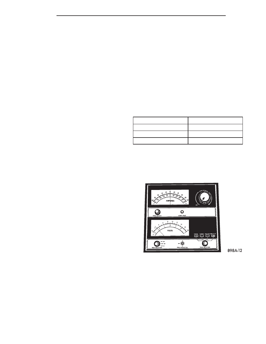
(1) Measure the voltage at battery posts with a

voltmeter accurate to 1/10 volt (Fig. 10). If below 10
volts, charge current will be low, and it could take
some time before it accepts a current in excess of a
few milliamperes. Such low current may not be
detectable on amp meters built into many chargers.

(2) Connect charger leads. Some chargers feature

polarity protection circuitry that prevents operation
unless charger is connected to battery posts correctly.
A completely discharged battery may not have
enough voltage to activate this circuitry. This may
happen even though the leads are connected properly.

(3) Battery chargers vary in the amount of voltage

and current they provide. For the time required for
the battery to accept measurable charger current at
various voltages, refer to Charging Rate Chart. If
charge current is still not measurable after charging

BATTERY CHARGING RATE

VOLTAGE

HOURS

16.0 VOLTS OR MORE

UP TO 4 HOURS

14.0 TO 15.9 VOLTS

UP TO 8 HOURS

13.9 VOLTS OR LESS

UP TO 16 HOURS

Fig. 10 Voltmeter Accurate to 1/10 Volt (Connected)

8A - 8

BATTERY

300M

times, the battery should be replaced. If charge cur-
rent is measurable during charging time, the battery
may be good, and charging should be completed in
the normal manner.

VISUAL INSPECTION

CAUTION:

Do not allow baking soda solution to

enter vent holes, as damage to battery can result.

(1) Clean top of battery with a solution of warm

water and baking soda.

(2) Apply soda solution with a bristle brush and

allow to soak until acid deposits loosen (Fig. 11).

(3) Rinse soda solution from battery with clear

water and blot battery dry with paper toweling. Dis-
pose of toweling in a safe manner. Refer to the
WARNINGS on top of battery.

(4) Inspect battery case and cover for cracks, leak-

age or damaged hold down ledge. If battery is dam-
aged replace it.

(5) Inspect battery tray for damage caused by acid

from battery. If acid is present, clean area with bak-
ing soda solution.

(6) Clean battery posts with a battery post clean-

ing tool (Fig. 12).

(7) Clean battery cable clamps with a battery ter-

minal cleaning tool (Fig. 13). Replace cables that are
frayed or have broken clamps.

Fig. 11 Cleaning Battery

Fig. 12 Cleaning Battery Post

Fig. 13 Cleaning Battery Cable Terminal

300M

BATTERY

8A - 9

SERVICE PROCEDURES (Continued)

REMOVAL AND INSTALLATION

BATTERY

WARNING: TO PROTECT THE HANDS FROM BAT-
TERY ACID, A SUITABLE PAIR OF HEAVY DUTY
RUBBER GLOVES, NOT THE HOUSEHOLD TYPE,
SHOULD BE WORN WHEN REMOVING OR SERVIC-
ING A BATTERY. SAFETY GLASSES ALSO SHOULD
BE WORN.

REMOVAL

(1) Turn the steering wheel all the way to the

right.

(2) Verify that the ignition switch and all accesso-

ries are OFF.

(3) Disconnect and isolate the negative battery

cable remote terminal from the remote battery post
(Fig. 14).

(4) Remove air cleaner housing. Refer to Group 14,

Fuel for service procedures.

(5) Remove battery splash shield. Refer to Group

23, Body for service procedures.

(6) Remove two short bolts to battery hold down.

(7) Slide battery rearward to disconnect the nega-

tive and positive battery terminals from battery.

(8) Slide battery toward rear of vehicle and lift out

through wheel well opening.

(9) Remove battery from vehicle.

INSTALLATION

For installation, reverse the above procedures.

Inspect and clean battery and attaching components
before installation.

WARNING:

DO NOT OVER TIGHTEN BATTERY

CABLE

CLAMPS,

DAMAGE

TO

CLAMPS

CAN

RESULT.

(1) Tighten clamp nuts to 8.5 N·m (75 in. lbs.)

torque.

SPECIFICATIONS

BATTERY

CRANKING RATING

The current battery can deliver for 30 seconds and

maintain a terminal voltage of 7.2 volts or greater at
specified temperature.

RESERVE CAPACITY RATING

The length of time a battery can deliver 25 amps

and maintain a minimum terminal voltage of 10.5
volts at 27°C (80°F).

TORQUE

DESCRIPTION

TORQUE

Battery Hold Down Clamp Bolt . . . . . . . . . . 14 N·m

(125 in. lbs.)

Fig. 14 Negative Battery Cable Remote Terminal

BATTERY SPECIFICATIONS

LOAD TEST

(AMPS)

COLD

CRANKING

RATING @ -18°C

(0°F)

RESERVE

CAPACITY

300 AMP

600 AMP

120 MINUTES

345 AMP

685 AMP

125 MINUTES

8A - 10

BATTERY

300M

STARTING

CONTENTS

page

page

GENERAL INFORMATION

INTRODUCTION . . . . . . . . . . . . . . . . . . . . . . . . . 1

DESCRIPTION AND OPERATION

MELCO STARTER . . . . . . . . . . . . . . . . . . . . . . . . 1
NIPPONDENSO STARTER . . . . . . . . . . . . . . . . . . 1
SUPPLY CIRCUIT AND CONTROL CIRCUIT . . . . 1

DIAGNOSIS AND TESTING

CONTROL CIRCUIT TEST . . . . . . . . . . . . . . . . . . 1
FEED CIRCUIT RESISTANCE TEST . . . . . . . . . . . 3

FEED CIRCUIT TEST . . . . . . . . . . . . . . . . . . . . . . 4
STARTING SYSTEM TEST . . . . . . . . . . . . . . . . . 4

REMOVAL AND INSTALLATION

SAFETY SWITCHES . . . . . . . . . . . . . . . . . . . . . . 6
STARTER . . . . . . . . . . . . . . . . . . . . . . . . . . . . . . 6
STARTER RELAY . . . . . . . . . . . . . . . . . . . . . . . . 7

SPECIFICATIONS

STARTER . . . . . . . . . . . . . . . . . . . . . . . . . . . . . . 7
TORQUE . . . . . . . . . . . . . . . . . . . . . . . . . . . . . . . 7

GENERAL INFORMATION

INTRODUCTION

The starting system has (Fig. 1):

• Ignition switch

• Starter relay

• Neutral starting and back-up switch

• Wiring harness

• Battery

• Starter motor with an integral solenoid
These components form two separate circuits. A

high amperage circuit that feeds the starter motor up
to 300+ amps, and a control circuit that operates on
less than 20 amps.

DESCRIPTION AND OPERATION

MELCO STARTER

The Melco is a permanent magnet starter motor. A

planetary gear train transmits power between starter
motor and pinion shaft. The fields have six perma-
nent magnets.

NIPPONDENSO STARTER

The Nippondenso is a reduction gear-field coil

starter motor.

SUPPLY CIRCUIT AND CONTROL CIRCUIT

The starter system consists of two separate cir-

cuits:

• A high amperage supply to feed the starter

motor.

• A low amperage circuit to control the starter

solenoid.

DIAGNOSIS AND TESTING

CONTROL CIRCUIT TEST

The starter control circuit has:
• Starter solenoid

• Starter relay

• Transmission range sensor, or Park/Neutral

Position switch with automatic transmissions

Fig. 1 Starting System

300M

STARTING

8B - 1


Content   ..  53  54  55  56   ..