Chrysler New Yorker. Manual - part 15


  Index      Chrysler     Chrysler New Yorker - service repair manual 1997-1999 year


Search            


Content   ..  13  14  15  16   ..


Chrysler New Yorker. Manual - part 15


(3) Install bolt attaching trailing arm to trailing

arm bracket on bottom of spindle (Fig. 16). Do not
fully tighten attaching bolt at this time.

(4) Install the disc brake adapter back on the spin-

dle. Install the 4 bolts attaching the disc brake
adapter to the rear spindle (Fig. 15). Tighten the disc
brake adapter mounting bolts to a torque of 115 N·m
(85 ft. lbs.).

(5) If vehicle is equipped with antilock brakes,

install the speed sensor head into the rear disc brake
adapter (Fig. 14). Tighten the speed sensor head
attaching bolt to a torque of 7 N·m (60 in. lbs.).

(6) Install the rear hub and bearing assembly on

the rear spindle. Install hub and bearing assembly
retaining washer and nut on spindle (Fig. 13).
Tighten the hub and bearing retaining nut to a
torque of 168 N·m (124 ft. lbs.).

(7) Install the rear brake disc on the hub.
(8) Carefully place rear brake caliper over rotor

and install on adapter. Tighten the caliper assembly
to adapter mounting bolts to a torque of 22 N·m (192

in. lbs.). Refer to Rear Disc Brakes in Group 5
Brakes in this service manual for required caliper
installation procedure.

(9) Install wheel and tire assembly on vehicle.

Tighten the wheel mounting stud nuts in proper
sequence until all nuts are torqued to half specifica-
tion. Then repeat the tightening sequence to the full
specified torque of 129 N·m (95 ft. lbs.).

(10) Lower vehicle to the ground.
(11) Tighten the lateral links to spindle attaching

bolt to a torque of 135 N·m (100 ft. lbs.).

(12) Tighten the trailing arm to spindle bracket

attaching bolt to a torque of 100 N·m (75 ft. lbs.).

(13) Check and reset rear wheel TOE to specifica-

tions if required.

REAR HUB AND BEARING

REMOVE

(1) Raise vehicle on jackstands or centered on a

frame contact type hoist. See Hoisting in the Lubrica-
tion and Maintenance section of this manual, for the
required lifting procedure to be used for this vehicle.

(2) Remove the rear wheel and tire assembly from

the vehicle.

(3) Remove the rear caliper assembly from the

adapter. Refer to Rear Disc Brakes in Group 5
Brakes of this Service manual for required caliper
removal procedure. After removing caliper assembly
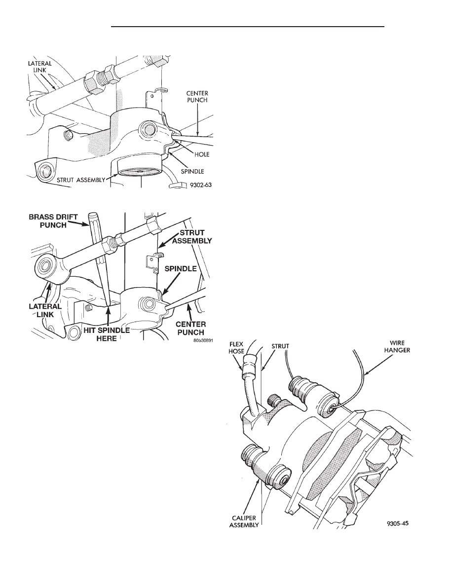
store caliper by hanging it from frame of vehicle (Fig.
21). Do not let weight of rear caliper assembly hang
from flexible brake hose.

(4) Remove rear braking disc from hub.

Fig. 19 Center Punch Inserted In Spindle

Fig. 20 Removing Spindle From Strut

Fig. 21 Storing Caliper

2 - 46

SUSPENSION

300M

REMOVAL AND INSTALLATION (Continued)

(5) Remove rear hub and bearing assembly cotter

pin and nut retainer (Fig. 22). Remove the hub and
bearing retaining nut and washer from the spindle
(Fig. 22). Then remove hub and bearing assembly
from spindle.

INSTALL

(1) Install the rear hub and bearing assembly on

the rear spindle. Install hub and bearing assembly
retaining washer and nut on spindle (Fig. 22).
Tighten the hub and bearing retaining nut to a
torque of 168 N·m (124 ft. lbs.). Install the nut
retainer and cotter pin (Fig. 22).

(2) Install the rear brake disc on the hub.
(3) Carefully place rear brake caliper over rotor and

install on adapter. Tighten the caliper assembly to
adapter mounting bolts to a torque of 22 N·m (192 in.
lbs.). Refer to Rear Disc Brakes in Group 5 Brakes in this
service manual for required caliper installation procedure.

(4) Install wheel and tire assembly on vehicle.

Tighten the wheel mounting stud nuts in proper
sequence until all nuts are torqued to half specifica-
tion. Then repeat the tightening sequence to the full
specified torque of 129 N·m (95 ft. lbs.).

(5) Lower vehicle to the ground.

LATERAL LINKS

The lateral links are only serviced as complete assem-

blies. The isolator bushings used in the lateral links are
not serviced as separate components. The left forward
lateral link requires a more involved removal and
installation procedure in order to remove the attaching
bolt at the crossmember. See procedures below for the
proper lateral link service procedure.

LEFT FORWARD LATERAL LINK

REMOVE

(1) Raise vehicle on jackstands or centered on a

frame contact type hoist. See Hoisting in the Lubrica-

tion and Maintenance section of this manual, for the
required lifting procedure to be used for this vehicle.

(2) Remove left rear wheel and tire assembly from

the vehicle.

(3) Remove the nut and bolt attaching the left lat-

eral links to the spindle (Fig. 23).

(4) Remove the nut attaching the left forward lat-

eral link to the rear suspension crossmember. The
bolt for the left front lateral link may not be
removed at this time. Remove the nut only.
Once the crossmember is lowered, the bolt can
be easily removed. 
Notice the forward link attach-
ing bolt faces rearward.

CAUTION: The bolts attaching the forward lateral
links to the crossmember must be installed with the
bolts pointing rearward (Fig. 24) to prevent damage
to the fuel tank and or fuel tubes. Also, the left rear
lateral arm attaching bolt to the crossmember is to
be installed pointing forward to prevent possible
damage to the fuel filler tube.

Fig. 22 Hub And Bearing Retaining Nut and Washer

Fig. 23 Lateral Link Attachment To Spindle

Fig. 24 Lateral Link Attachment To Crossmember

300M

SUSPENSION

2 - 47

REMOVAL AND INSTALLATION (Continued)

(5) Remove the screw securing the brake tubes to

the left stabilizer bar isolator bushing retainer.

(6)

Remove the 4 bolts attaching both stabilizer

bar isolator bushing retainers to the frame rails (the
2 rearward attaching bolts also attach the front cor-
ners of the rear suspension crossmember in place).
Allow the stabilizer bar to hang down out of the way.

(7) Remove the screw securing the fuel filler neck

to the left frame rail.

(8) Position a transmission jack under the fuel tank.
(9) Remove the attaching bolts securing both fuel

tank mounting straps. First, remove the right, then the
left attaching bolt. Allow the straps to hang down.

(10) Lower the transmission jack and fuel tank

just enough to allow for removal of the lateral link
attaching bolt at the crossmember.

(11) Remove the left forward lateral link from the

crossmember.

INSTALL

CAUTION: The bolts attaching the forward lateral
links to the crossmember must be installed with the
bolts pointing rearward (Fig. 24) to prevent damage
to the fuel tank and or fuel tubes. Also, the left rear
lateral arm attaching bolt to the crossmember is to
be installed pointing forward to prevent possible
damage to the fuel filler tube.

(1) Attach the left forward lateral link to cross-

member. Install mounting bolt through the front of
the crossmember mount towards the rear. Install the
lateral link attaching nut, but DO NOT fully tighten
at this time.

CAUTION: Tightening the lateral link attaching bolt
at this point will cause the bushing to contort when
the vehicle is at curb riding height, thus contribut-
ing to premature failure of the lateral link bushings.

(2) Raise the fuel tank up into mounting position.
(3) Reattach the fuel tank straps, securing the fuel

tank in place.

(4) Remove transmission jack supporting the fuel

tank.

(5) Reinstall the fuel filler neck attaching screw

and secure the fuel filler neck to the left frame rail.

(6) Install the 4 bolts attaching both stabilizer bar

isolator bushing retainers to the frame rails (the 2
rearward attaching bolts attach the front corners of
the rear suspension crossmember in place). Tighten
the forward stabilizer bar isolator bushing retainer
attaching bolts to 40 N·m (30 ft. lbs.). Tighten the 2
rearward stabilizer bar isolator bushing retainer
attaching bolts (which also serve as the front cross-
member attaching bolts) to 100 N·m (75 ft. lbs.).

(7) Install the screw securing the brake tubes to

the left stabilizer bar isolator bushing retainer.

(8) Install the lateral links on the spindle. Install,

but DO NOT fully tighten the attaching bolt and nut
at this time (Fig. 23).

CAUTION: Tightening the lateral link attaching bolt
at this point will cause the bushing to contort when
the vehicle is at curb riding height, thus contributing
to premature failure of the lateral link bushings.

(9) Install rear wheel and tire assembly on vehicle.
(10) Tighten the wheel mounting stud nuts in

proper sequence until all nuts are torqued to half
specification. Then repeat the tightening sequence to
the full specified torque of 129 N·m (95 ft. lbs.).

(11) Lower vehicle to the ground.
(12) Tighten lateral arm to crossmember attaching

bolt 95 N·m (70 ft. lbs.).

(13) Tighten lateral arm to spindle attaching bolt

135 N·m (100 ft. lbs.).

(14) Check and reset rear wheel TOE to specifica-

tions if required.

LEFT REAR AND BOTH RIGHT LATERAL
LINKS

REMOVE

(1) Raise vehicle on jackstands or centered on a

frame contact type hoist. See Hoisting in the Lubrica-
tion and Maintenance section of this manual, for the
required lifting procedure to be used for this vehicle.

(2) Remove rear wheel and tire assembly from the

vehicle.

(3) Remove the nut and bolt attaching the left lat-

eral links to the spindle (Fig. 25).

(4) Remove the nut and bolt attaching the lateral link

to the rear suspension crossmember. Note the direction
in which the lateral arm attaching bolt is installed.

Fig. 25 Lateral Link Attachment To Spindle

2 - 48

SUSPENSION

300M

REMOVAL AND INSTALLATION (Continued)

CAUTION: The bolts attaching the forward lateral
links to the crossmember must be installed with the
bolts pointing rearward (Fig. 26) to prevent damage
to the fuel tank and or fuel tubes. Also, the left rear
lateral arm attaching bolt to the crossmember is to
be installed pointing forward to prevent possible
damage to the fuel filler tube.

(5) Remove the lateral link from the crossmember.

INSTALL

(1) Attach the lateral link to crossmember. Rear

lateral link attachment bolts should be installed from
the rear and point forward. Forward lateral link
attachment bolts should be installed from the front
and point rearward.

CAUTION: The bolts attaching the forward lateral
links to the crossmember must be installed with the
bolts pointing rearward (Fig. 26) to prevent damage
to the fuel tank and or fuel tubes. Also, the left rear
lateral arm attaching bolt to the crossmember is to
be installed pointing forward to prevent possible
damage to the fuel filler tube.

(2) Install the attaching nut, but DO NOT tighten

at this time.

CAUTION: Tightening the lateral link attaching bolt
at this point will cause the bushing to contort when
the vehicle is at curb riding height, thus contributing
to premature failure of the lateral link bushings.

(3) Install the lateral links on the spindle. Install,

but DO NOT fully tighten the attaching bolt and nut
at this time (Fig. 25).

(4) Install rear wheel and tire assembly on vehicle.
(5) Tighten the wheel mounting stud nuts in

proper sequence until all nuts are torqued to half

specification. Then repeat the tightening sequence to
the full specified torque of 129 N·m (95 ft. lbs.).

(6) Lower vehicle to the ground.
(7) Tighten lateral arm to crossmember attaching

bolt and nut to 95 N·m (70 ft. lbs.).

(8) Tighten lateral arm to spindle attaching bolt

and nut to 135 N·m (100 ft. lbs.).

(9) Check and reset rear wheel TOE to specifica-

tions if required.

TRAILING ARM

REMOVE

(1) Raise vehicle on jackstands or centered on a

frame contact type hoist. See Hoisting in the Lubri-
cation and Maintenance section of this manual, for
the required lifting procedure to be used for this
vehicle.

(2) Remove the rear wheel and tire assembly from

the vehicle.

(3) Remove the bolt attaching the trailing arm to

the bracket on the bottom of the spindle (Fig. 27).

(4) Remove the 4 bolts attaching the arm forward

mounting bracket to the frame rail and rear torque
box (Fig. 28).

(5) Remove the trailing arm and forward mounting

bracket from vehicle.

(6) Remove the bolt attaching the trailing arm to

the mounting bracket.

INSTALL

CAUTION: When the trailing arm is installed to its
mounting bracket, it is important to set an offset
angle of 5 degrees before tightening the attaching
bolt. Otherwise, the bushing will be contorted when
the vehicle is at normal riding height. This angle
cannot be set once the trailing arm and bracket are
installed on the vehicle.

Fig. 27 Trailing Arm To Bracket Bolt

Fig. 26 Lateral Link Attachment To Crossmember

300M

SUSPENSION

2 - 49

REMOVAL AND INSTALLATION (Continued)


Content   ..  13  14  15  16   ..