Chrysler New Yorker. Manual - part 11


  Index      Chrysler     Chrysler New Yorker - service repair manual 1997-1999 year


Search            


Content   ..  9  10  11  12   ..


Chrysler New Yorker. Manual - part 11


(16) Tighten the wheel mounting nuts in proper

sequence until all nuts are torqued to half specifica-
tion. Repeat the tightening sequence to the full spec-
ified torque of 129 N·m (95 ft. lbs.).

(17) Lower vehicle to the ground.

WHEEL MOUNTING STUDS

CAUTION: If a wheel attaching stud needs to be
replaced in the hub and bearing assembly the studs
CANNOT be hammered out of the hub flange. If a
stud is removed by hammering it out of the bearing
flange, damage to the hub and bearing assembly
will occur leading to premature bearing failure.

CAUTION: The following procedure and special
tools shown

MUST

be used when replacing wheel

attaching studs.

NOTE: The hub and bearing assembly does not
require

removal

from

the

steering

knuckle

to

replace wheel attaching studs in the hub and bear-
ing assembly.

REMOVE

(1) Raise vehicle on jackstands or centered on a

frame contact type hoist. See Hoisting in the Lubri-
cation and Maintenance section of this manual, for
the required lifting procedure to be used for this
vehicle.

(2) Remove the 2 guide pin bolts mounting the cal-

iper assembly to the steering knuckle (Fig. 61).
Remove the caliper from the front steering knuckle.
Refer to Disc Brake Caliper in the Removal And
Installation Section in the Brake Group of this ser-
vice manual for the caliper removal procedure.

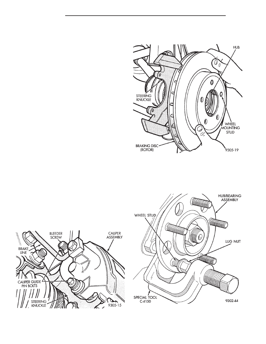
(3) Remove rotor from hub by pulling it straight

off wheel mounting studs (Fig. 62).

(4) Install a lug nut on the wheel stud to be

removed from the hub and bearing assembly (Fig. 63)
so the threads on stud are even with end of lug nut.
Install Remover, Special Tool C-4150 on hub and
bearing assembly flange and wheel stud (Fig. 63).

Fig. 61 Caliper Mounting

Fig. 62 Removing Rotor

Fig. 63 Removing Wheel Stud From Hub And

Bearing

2 - 30

SUSPENSION

300M

REMOVAL AND INSTALLATION (Continued)

(5) Tighten down on special tool, to push wheel

stud out of the hub and bearing assembly. When
shoulder of wheel stud is past flange remove special
tool from hub and bearing assembly. Remove lug nut
from stud and remove wheel stud from flange.

INSTALL

(1) Install wheel stud into of hub and bearing

assembly. Install washers on wheel stud, then install
a wheel lug nut on stud with flat side of lug nut
against washers (Fig. 64).

(2) Tighten the wheel lug nut, pulling the wheel

stud into the flange of the hub and bearing assembly.
When the head of the stud is fully seated against the
bearing flange, remove lug nut and washers from
wheel stud.

(3) Install the rotor on the hub and bearing assem-

bly (Fig. 62).

(4) Install front brake caliper back over braking

disc and align with caliper mounting holes on steer-
ing knuckle. Refer to Disc Brake Caliper in the
Removal And Installation Section in the Brake Group
of this service manual for the caliper installation pro-
cedure. Install the caliper to steering knuckle guide
pin bolts (Fig. 61) and tighten to a torque of 19 N·m
(168 in. lbs.).

(5) Install wheel and tire assembly on vehicle.

Tighten the wheel mounting stud nuts in proper
sequence until all nuts are torqued to half specifica-
tion. Then repeat the tightening sequence to the full
specified torque of 129 N·m (95 ft. lbs.).

(6) Lower the vehicle to the ground.

DISASSEMBLY AND ASSEMBLY

MacPHERSON STRUT

The front strut is not serviced and must be

replaced as an assembly if found to be defective. The
strut is available with 2 calibrations, be sure strut is
replaced with an assembly of the same calibration.

The components of the strut assembly listed below

are replaceable if found to be defective.

• Coil spring

• Dust shield

• Mount assembly

• Seat And Bearing

• Jounce Bumper

• Jounce Bumper Cup

• Upper Spring Isolator

• Lower Spring Isolator

• Shaft Nut

DISASSEMBLY

(1) Remove strut assembly requiring service from

the vehicle. Refer to MacPherson Strut in the
Removal And Installation Section in this group of the
service manual for the required procedure.

(2) Position the strut assembly in a vise. Using

paint or equivalent, mark the strut unit, lower spring
isolator, spring and upper strut mount for indexing of
the parts at assembly.

CAUTION: When installing spring compressor on
coil spring, do not position the spring compressor
on the sleeves of the coil spring. Positioning the
spring compressor on the sleeves could cause the
sleeve to dislodge from the coil spring when it is
compressed. This would result in the required
replacement of the coil spring.

WARNING: DO NOT INSTALL THE SPRING COM-
PRESSOR ON THE COIL SPRING IN AN AREA OF
THE SPRING COVERED BY A SLEEVE. IF THE
SLEEVE

MOVES

WHEN

COMPRESSING

THE

SPRING, THE SPRING COULD COME OUT OF COM-
PRESSOR RESULTING IN PERSONAL INJURY.

(3) Attach OTC shoe 7526, or the equivalent, on

upper end of OTC Spring Compressor 7520, or the
equivalent compressor. Attach LH lower adapter tool on
lower end of Spring Compressor. Position Spring Com-
pressor on the strut assembly spring. The upper shoe
will attach to the top rung of coil spring, while the
lower adapter will attach to the lower end of the strut.
Compress coil spring until all load is removed from the
strut upper mount, where the spring contacts it.

(4) Install Strut Shaft Nut Socket, Special Tool

6864, on strut shaft nut. Using a 10 mm socket on

Fig. 64 Installing Wheel Stud Into Hub And Bearing

300M

SUSPENSION

2 - 31

REMOVAL AND INSTALLATION (Continued)

end of strut shaft to keep strut shaft from turning,
remove strut shaft nut.

(5) Remove the upper strut mount assembly, bear-

ing and seat, dust shield, and coil spring, from the
strut as a unit.

(6) Remove the jounce bumper, and jounce bumper

cup, from the strut.

(7) Carefully release the spring compressor tension

on the coil spring.

(8) Remove the coil spring from the strut.
(9) Remove the coil spring isolator from the lower

spring seat on the strut (Fig. 65).

(10) Remove the upper spring isolator from the

seat and bearing assembly.

(11) Inspect all disassembled components for signs

of abnormal wear or failure replacing any compo-
nents as required. Inspect strut unit for signs of
abnormal oil leakage and for loss of gas charge. To
check for loss of gas charge in strut unit. Push strut
shaft into body of strut and release, strut shaft
should return to its fully extended position. If strut
shaft does not return to its fully extended position
replace strut unit.

ASSEMBLY

(1) Install the original, or a new if required, lower

spring isolator on the strut (Fig. 65). Tabs on the iso-
lator will align it on the strut spring seat.

(2) Install the original, or a new if required, upper

spring isolator on the bearing and seat.

(3) Install the coil spring on the strut, setting it

into the groove in the lower isolator provided for it.

(4) Compress the spring approximately the same

amount it was compressed before removal.

(5) Position the seat and bearing assembly (with

dust shield) on the top of the coil spring. The end of
the coil spring should fit into the notch molded into
the seat and bearing assembly, or align the paint
marks made previously (if available).

(6) Install jounce bumper, and jounce bumper cup,

onto shaft of strut.

CAUTION: Before installing the upper mount, make
sure the correct upper mount is being installed on
the strut. DO NOT install a right mount on a left
front strut or a left mount on a right front strut.
Incorrect mount installation may cause poor vehicle
ride and steering feel, and excessive front end
noise. A lead or drift condition may also be the
result. Left and Right mounts look similar, but are
different from one another. Looking down at the top
of the upper mount, 2 tabs can be seen, (Fig. 66)
and (Fig. 67), down inside the mount center well. A
rectangular hole can be seen on the edge of the
mount mounting surface (Fig. 66) and (Fig. 67). This
is always in the 10 o’clock position when observing
rubber tab positioning, whether a left or right mount
is being observed. Once this hole is located in the
10 o’clock position, the tabs should be in the posi-
tions as shown (Fig. 66) and (Fig. 67). The right
upper mount should also have a white dot painted
on its mounting face.

(7) Install the upper mount on top of the seat and

bearing assembly.

(8) Install the strut shaft nut. Install Strut Shaft

Nut Socket, Special Tool 6864, on strut shaft nut.
Using a 10 mm socket on end of strut shaft to keep
strut shaft from turning, tighten strut shaft nut to a
torque of 94 N·m (70 ft. lbs.).

(9) Loosen the spring compressor until the spring

is seated and all tension is relieved from the spring
compressor.

(10) Verify upper mount does not bind.
(11) Remove the coil spring compressor.
(12) Install the strut assembly on the vehicle.

Refer to MacPherson Strut in the Removal And
Installation Section in this group of the service man-
ual for the required procedure.

Fig. 65 Spring Isolator

Fig. 66 Left Front Strut Upper Mount

2 - 32

SUSPENSION

300M

DISASSEMBLY AND ASSEMBLY (Continued)

TENSION STRUT

To replace the tension strut, the tension strut and

lower control arm first MUST be removed as an
assembly from the vehicle.

DISASSEMBLY

(1) Raise vehicle using a frame contact type hoist

or supported as required using jack stands. See
Hoisting in the Lubrication and Maintenance group
of this service manual for the required hoisting or
jacking procedure to be used for this vehicle.

(2) Remove the wheel and tire from the car.
(3) Remove lower control arm and tension strut as

an assembly from the vehicle. See Lower Control
Arm Removal in this section of the service manual
for the required removal procedure.

(4) Separate the tension strut from the lower con-

trol arm assembly.

(5) Inspect tension strut bushing in lower control

arm for excessive wear or deterioration. If tension
strut bushing is found to be defective replace lower
control tension strut bushing at this time. Refer to
Lower Control Arm Bushing Service in this section of
the service for tension strut removal and installation
procedure.

ASSEMBLY

(1) Position tension strut in lower control as shown

in (Fig. 68), with word FRONT stamped in tension
strut positioned away from control arm (Fig. 68).
With an open end wrench on flat of tension strut to
keep tension strut from turning. Tighten NEW ten-
sion strut to lower control retaining nut to a torque
of 130 N·m (95 ft. lbs.).

(2) Install lower control arm and tension strut as

an assembly back on the vehicle. See Lower Control
Arm Installation in this section of the service manual
for the required installation procedure.

(3) Install washer on end of tension strut (Fig. 69).

Install a NEW tension strut to cradle bracket

nut, on tension strut (Fig. 69). Tighten the tension
strut to cradle bracket retaining nut to a torque of
130 N·m (95 ft. lbs.). When torquing tension strut
nut, keep tension strut from turning by holding ten-
sion strut at flat using a large open end wrench (Fig.
69).

(4) Install the wheel and tire assembly.
(5) Tighten the wheel mounting stud nuts in

proper sequence until all nuts are torqued to half
specification. Then repeat the tightening sequence to
the full specified torque of 129 N·m (95 ft. lbs.).

(6) Lower the vehicle to the ground so the suspen-

sion is supporting the vehicles full weight (control
arm at design height). Tighten the lower control arm
pivot bushing to cradle bracket attaching bolt (Fig.
70) to a torque of 142 N·m (105 ft. lbs.).

LOWER CONTROL ARM PIVOT BUSHING

To replacement the lower control arm pivot bush-

ing, the control arm and tension strut assembly must

Fig. 68 Tension Strut Installed In Lower Control

Arm.

Fig. 69 Tension Strut To Cradle Mounting

Fig. 67 Right Front Strut Upper Mount

300M

SUSPENSION

2 - 33

DISASSEMBLY AND ASSEMBLY (Continued)


Content   ..  9  10  11  12   ..