Chrysler Crossfire. Manual - part 9


  Index      Chrysler     Chrysler Crossfire - service repair manual 2005 year


Search            


Content   ..  7  8  9  10   ..


Chrysler Crossfire. Manual - part 9


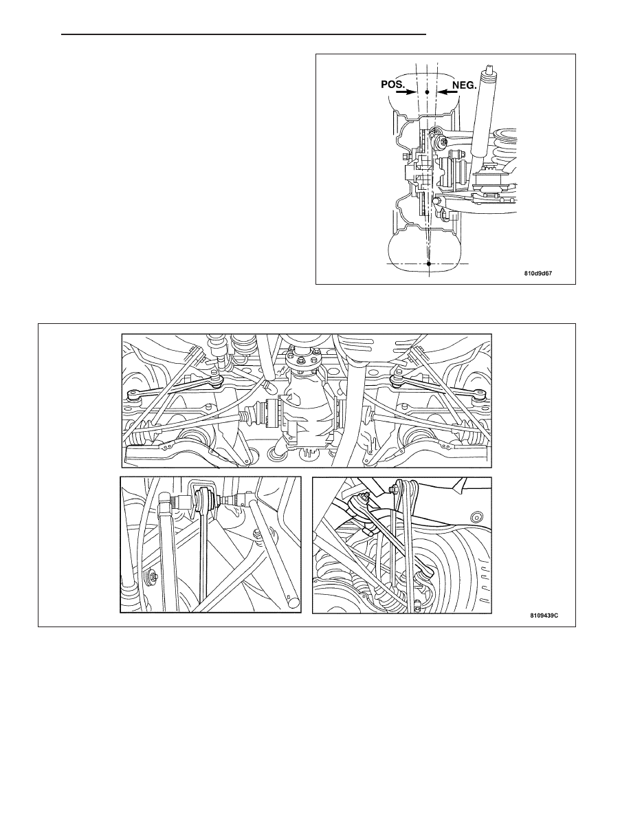
3. Check the rear axle camber. (POS+) = Positive

Camber, (NEG-) = Negative Camber. The camber
on the rear axle is not adjustable. If substantial
deviations in the rear axle camber are found, the
cause may be one of the following: (Refer to 2 -
SUSPENSION/WHEEL ALIGNMENT - SPECIFICA-
TIONS).

Too great a difference in the vehicle level
between the right and left-hand sides of vehicle.

Camber strut bent.

Accident damage to the frame floor. Level differ-
ences at the mounting points for the rear axle
carrier between the left and right sides of the
body. Experience shows that bending caused by
an accident also has an effect on the toe.

STANDARD PROCEDURE - CHECKING AND ADJUSTING REAR AXLE TOE

1. Check the vehicle level at the front and rear axles and adjust if necessary. (Refer to 2 - SUSPENSION/WHEEL

ALIGNMENT - STANDARD PROCEDURE).

2. Check the vehicle level at the front and rear axles with an electronic inclinometer and adjust if necessary. (Refer

to 2 - SUSPENSION/WHEEL ALIGNMENT - STANDARD PROCEDURE).

3. Adjust the toe with the cam bolt on the mounting of the left and right tie rod on rear axle carrier.

ZH

WHEEL ALIGNMENT

2 - 11

SPECIFICATIONS

SPECIFICATIONS - WHEEL ALIGNMENT

DESCRIPTION

SPECIFICATION

Vehicle level - front axle

1.4° (-2.1/+1.4)

Vehicle level - rear axle

0.4° (±0.8)

Ball point position

30,5±2 mm

Front axle toe-in

0° 20’±10’

Toe-out on turns with wheel on the inside of the curve

steered through 20°

-1° 25’±30’

Total rear axle toe

0 ° 33’±7’

ALIGNMENT SPECIFICATIONS

Front Axle Toe

2.5°

Rear Axle Toe

1.2°

Front Camber

-1° 13’ (-1.22°)

Front Caster

5° 12’ (5.20°)

Rear Camber

-1° 08’ (-1.13°)

Permissible difference in front axle camber between

right and left side of vehicle

20’

SPECIFICATIONS - TORQUE

TORQUE SPECIFICATIONS

DESCRIPTION

N·m

Ft. Lbs.

In. Lbs.

Steering idler arm to bearing

bushing

30

22

266

Repair Nut

120

88.5

1060

Lock Nut

50

37

443

Cam bolt, rear axle tie rod

70

52

620

2 - 12

WHEEL ALIGNMENT

ZH

FRONT SUSPENSION

TABLE OF CONTENTS

page

page

FRONT SUSPENSION

STANDARD PROCEDURE - ADJUSTING

FRONT WHEEL BEARINGS

. . . . . . . . . . . . . . 13

SPECIFICATIONS - TORQUE

. . . . . . . . . . . . . . 14

SPECIAL TOOLS

. . . . . . . . . . . . . . . . . . . . . . . . 15

KNUCKLE

DESCRIPTION

. . . . . . . . . . . . . . . . . . . . . . . . . 16

REMOVAL

. . . . . . . . . . . . . . . . . . . . . . . . . . . . . 16

INSTALLATION

. . . . . . . . . . . . . . . . . . . . . . . . . 20

HUB / BEARING

DESCRIPTION

. . . . . . . . . . . . . . . . . . . . . . . . . 22

REMOVAL

. . . . . . . . . . . . . . . . . . . . . . . . . . . . . 23

INSTALLATION

. . . . . . . . . . . . . . . . . . . . . . . . . 25

LOWER BALL JOINT

REMOVAL

. . . . . . . . . . . . . . . . . . . . . . . . . . . . . 27

INSTALLATION

. . . . . . . . . . . . . . . . . . . . . . . . . 30

LOWER CONTROL ARM

REMOVAL

. . . . . . . . . . . . . . . . . . . . . . . . . . . . . 32

INSTALLATION

. . . . . . . . . . . . . . . . . . . . . . . . . 34

UPPER CONTROL ARM

REMOVAL

. . . . . . . . . . . . . . . . . . . . . . . . . . . . . 36

INSTALLATION

. . . . . . . . . . . . . . . . . . . . . . . . . 37

SHOCK

REMOVAL

. . . . . . . . . . . . . . . . . . . . . . . . . . . . . 37

INSTALLATION

. . . . . . . . . . . . . . . . . . . . . . . . . 38

SPRING

REMOVAL

. . . . . . . . . . . . . . . . . . . . . . . . . . . . . 39

INSTALLATION

. . . . . . . . . . . . . . . . . . . . . . . . . 40

STABILIZER BAR

REMOVAL

. . . . . . . . . . . . . . . . . . . . . . . . . . . . . 42

INSTALLATION

. . . . . . . . . . . . . . . . . . . . . . . . . 43

FRONT SUSPENSION

STANDARD PROCEDURE - ADJUSTING FRONT WHEEL BEARINGS

1. Remove the wheel and tire assembly.

2. Install a wheel bolt (1) on the opposite side from the brake rotor retaining bolt (5).

3. Press the brake pads back in the brake caliper making sure they do not come in contact with the brake rotor.

4. Remove the dust cap (2).

ZH

FRONT SUSPENSION

2 - 13

5. Loosen the hub nut bolt. Turn the hub nut (4) back until a slight end play is achieved.

6. Attach a dial indicator.

CAUTION: Do not turn the wheel hub while taking the measurement.

7. Adjust the wheel bearing end play by turning the hub nut (4) in stages while pushing and pulling the rotor firmly

back and forth. Adjust end play to 0.01–0.02 mm.

8. Tighten the hub nut bolt to 11 N·m (8 ft. lbs.) and recheck the wheel bearing end play.

9. Remove the dial indicator.

10. Install the wheel hub dust cap (2).

11. Remove the wheel bolt from the rotor.

12. Install the front wheel and tire assembly.

SPECIFICATIONS - TORQUE

TORQUE SPECIFICATIONS

DESCRIPTION

N·m

Ft. Lbs.

In. Lbs.

Front Shock Absorber

Upper Nut

18

13

159

Front Shock Absorber

Lower Nut

55

41

487

Front Sway Bar To Lower

Control Arm Nut

20

15

177

Front Sway Bar Bushing

Nuts

M10

40

30

354

M8

20

15

177

Front Sway Bar To Frame

Nut

60

44

531

Upper Control Arm Joint

To Steering Knuckle

45

33

398

Clamping Nut

11

8

97

Lower Ball Joint To

Steering Knuckle

140

103

1240

Lower Ball Joint To lower

Control Arm

105

77

929

Upper Control Arm To

Body Nut

65

50

575

Lower Control Arm To

Frame Nut

120

88

1060

2 - 14

FRONT SUSPENSION

ZH


Content   ..  7  8  9  10   ..