Chrysler 300/300 Touring/300C, Dodge Magnum. Manual - part 825


  Index      Chrysler     Chrysler 300/300 Touring/300C, Dodge Magnum - service repair manual


Search            


Content   ..  823  824  825  826   ..


Chrysler 300/300 Touring/300C, Dodge Magnum. Manual - part 825


When Monitored:
With the ignition on.

Set Condition:
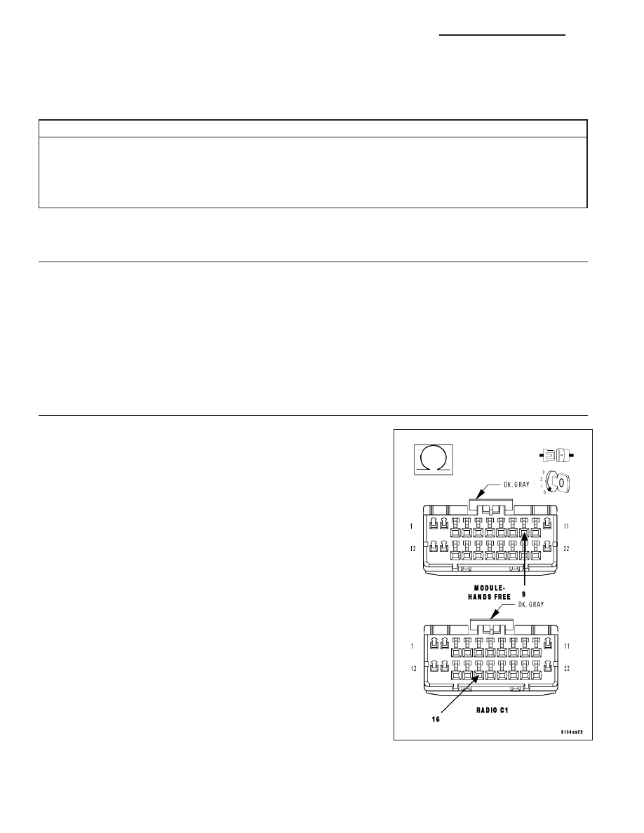
The Hands Free Module detects high voltage on the (X704) Right Audio Output circuit.

Possible Causes

(X704) RIGHT AUDIO OUTPUT CIRCUIT OPEN

(X795) COMMON AUDIO OUTPUT CIRCUIT OPEN

(X704) RIGHT AUDIO OUTPUT CIRCUIT SHORT TO VOLTAGE

HANDS FREE MODULE

Diagnostic Test

1.

CHECK FOR ACTIVE DTC

With the scan tool, read the active DTC’s.

Cycle the ignition switch from off to on at least 5 times, leaving the ignition on for a minimum of 90 seconds per
cycle.

With the scan tool, read the active DTC’s.

Does the scan tool display this DTC as active?

Yes

>> Go To 2

No

>> If the DTC is stored, check for an intermittent condition. Visually inspect the related wiring harness con-

nectors. Look for broken, bent, pushed out, or corroded terminals.

2.

(X704) RIGHT AUDIO OUTPUT CIRCUIT OPEN

Turn the ignition off.

Disconnect the Hands Free Module harness connector.

Disconnect the Radio C1 harness connector.

Measure the resistance of the (X704) Right Audio Output circuit
between the HFM connector and the radio connector.

Is the resistance below 5.0 ohms?

Yes

>> Go To 3

No

>> Repair the (X704) Right Audio Output circuit for an open.

Perform BODY VERIFICATION TEST – VER 1. (Refer to
BODY VERIFICATION TEST – VER 1).

8T - 16

NAVIGATION/TELECOMMUNICATION - ELECTRICAL DIAGNOSTICS

LX

3.

(X795) COMMON AUDIO OUTPUT CIRCUIT OPEN

Measure the resistance of the (X795) Common Audio Output circuit
between the HFM connector and the radio connector.

Is the resistance below 5.0 ohms?

Yes

>> Go To 4

No

>> Repair the (X795) Common Audio Output circuit for an

open.

Perform BODY VERIFICATION TEST – VER 1. (Refer to
BODY VERIFICATION TEST – VER 1).

4.

(X704) RIGHT AUDIO OUTPUT CIRCUIT SHORT TO VOLTAGE

Turn the ignition on.

Measure the voltage of the (X704) Right Audio Output circuit.

Is the voltage above 1.0 volts?

Yes

>> Repair the (X704) Right Audio Output circuit for a short to

voltage.

Perform BODY VERIFICATION TEST – VER 1. (Refer to
BODY VERIFICATION TEST – VER 1).

No

>> Inspect the wiring and connectors for damage or shorted

circuits. If ok, replace and program the Hands Free Module
in accordance with the service information.

Perform BODY VERIFICATION TEST – VER 1. (Refer to
BODY VERIFICATION TEST – VER 1).

LX

NAVIGATION/TELECOMMUNICATION - ELECTRICAL DIAGNOSTICS

8T - 17

B1435-VOICE RECOGNITION/PHONE SWITCH INPUT CIRCUIT PERFORMANCE

For a complete wiring diagram Refer to Section 8W.

8T - 18

NAVIGATION/TELECOMMUNICATION - ELECTRICAL DIAGNOSTICS

LX

When Monitored:
With the ignition on.

Set Condition:
The Hands Free Module detects an invalid voltage signal on the (X730) Voice Recognition/Phone Switch Sig-
nal circuit.

Possible Causes

INSIDE REAR VIEW MIRROR

HANDS FREE MODULE

Diagnostic Test

1.

CHECK FOR ACTIVE DTC

With the scan tool, read the active DTC’s.

Cycle the ignition switch from off to on at least 5 times, leaving the ignition on for a minimum of 90 seconds per
cycle.

With the scan tool, read the active DTC’s.

Does the scan tool display this DTC as active?

Yes

>> Go To 2

No

>> If the DTC is stored, check for an intermittent condition. Visually inspect the related wiring harness con-

nectors. Look for broken, bent, pushed out, or corroded terminals.

2.

CHECK THE VOLTAGE OF THE (X730) VOICE RECOGNITION/PHONE SWITCH SIGNAL

Turn the ignition off.

Disconnect the Inside Rear View Mirror C2 harness connector.

Turn the ignition on.

With the scan tool, monitor the VR Phone Switch voltage.

While monitoring the VR Phone Switch voltage, momentarily connect a
jumper wire between the (X730) Voice Recognition/Phone Switch Sig-
nal circuit and ground.

NOTE: The scan tool sensor voltage should switch from above 4.7
volts when the jumper is not connected to below 0.6 volts when
the jumper is connected.

Does the sensor voltage switch from above 4.7 volts to below
0.6 volt as described?

Yes

>> Replace the Inside Rear View Mirror in accordance with the

service information.

Perform BODY VERIFICATION TEST – VER 1. (Refer to
BODY VERIFICATION TEST – VER 1).

No

>> Inspect the wiring and connectors for damage or shorted

circuits. If ok, replace and program the Hands Free Module
in accordance with the service information.

Perform BODY VERIFICATION TEST – VER 1. (Refer to BODY VERIFICATION TEST – VER 1).

LX

NAVIGATION/TELECOMMUNICATION - ELECTRICAL DIAGNOSTICS

8T - 19


Content   ..  823  824  825  826   ..