Chrysler 300/300 Touring/300C, Dodge Magnum. Manual - part 771
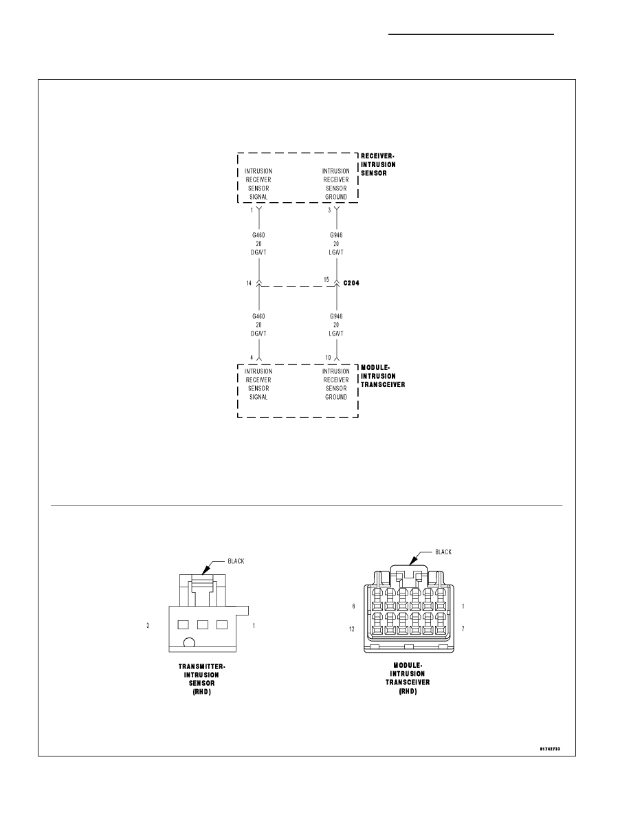
B1A3B–SECURITY RECEIVER SENSOR CIRCUIT HIGH
For a complete wiring diagram Refer to Section 8W.
8Q - 52
VEHICLE THEFT SECURITY - ELECTRICAL DIAGNOSTICS
LX
|
|
|
B1A3B–SECURITY RECEIVER SENSOR CIRCUIT HIGH For a complete wiring diagram Refer to Section 8W. 8Q - 52 VEHICLE THEFT SECURITY - ELECTRICAL DIAGNOSTICS LX |