Chrysler 300/300 Touring/300C, Dodge Magnum. Manual - part 646


  Index      Chrysler     Chrysler 300/300 Touring/300C, Dodge Magnum - service repair manual


Search            


Content   ..  644  645  646  647   ..


Chrysler 300/300 Touring/300C, Dodge Magnum. Manual - part 646


3.

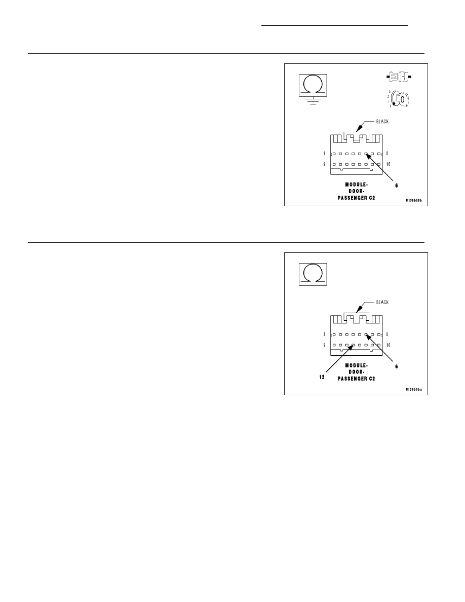
(E34) PASSENGER WINDOW EXPRESS SWITCH ILLUMINATION DRIVER CIRCUIT SHORT TO GROUND

Turn the ignition off.

Turn the park lamps off.

Disconnect the Passenger Door Module C2 connector.

Measure the resistance between Ground and the (E34) Passenger Win-
dow Express Switch Illumination Driver circuit.

Is the resistance below 10000.0 ohms?

Yes

>> Repair the (E34) Passenger Window Express Switch Illumi-

nation Driver circuit for a short to ground.

Perform BODY VERIFICATION TEST - VER 1. (Refer to
BODY VERIFICATION TEST – VER 1).

No

>> Go To 4

4.

(E34) PASSENGER WINDOW EXPRESS SWITCH ILLUMINATION DRIVER CIRCUIT SHORT TO (Q936)
PASSENGER WINDOW EXPRESS SWITCH RETURN

Measure the resistance between the (E34) Passenger Window Express
Switch Illumination Driver circuit and the (Q936) Passenger Window
Express Switch Return circuit.

Is the resistance below 10000.0 ohms?

Yes

>> Repair the (E34) Passenger Window Express Switch Illumi-

nation Driver circuit for a short to the (Q936) Passenger
Window Express Switch Return circuit.

Perform BODY VERIFICATION TEST - VER 1. (Refer to
BODY VERIFICATION TEST – VER 1).

No

>> Replace the Passenger Door Module.

Perform BODY VERIFICATION TEST - VER 1. (Refer to
BODY VERIFICATION TEST – VER 1).

8N - 282

POWER WINDOWS - ELECTRICAL DIAGNOSTICS

LX

B16A5–PASSENGER WINDOW SWITCH BACKLIGHTING CIRCUIT HIGH – PDM

For a complete wiring diagram Refer to Section 8W.

LX

POWER WINDOWS - ELECTRICAL DIAGNOSTICS

8N - 283

When Monitored:
Whenever the power is turned off to the module and it goes from awake to sleep mode.

Set Condition:
When the Passenger Window Express Switch Illumination Driver circuit is above 2.5 volts for over 15 ms. and
the switch illumination output is turned off.

Possible Causes

(E34) PASSENGER WINDOW EXPRESS SWITCH ILLUMINATION DRIVER CIRCUIT SHORT TO VOLTAGE

WINDOW/DOOR LOCK SWITCH SHORTED

PASSENGER DOOR MODULE (PDM)

Diagnostic Test

1.

TEST FOR INTERMITTENT CONDITION

Turn the ignition on.

With the scan tool, record and erase DTC’s

Ensure the passenger window lock out switch is off.

Wait 30 seconds.

With the scan tool, read DTC’s.

Does the scan tool display B16A5–PASSENGER WINDOW SWITCH BACKLIGHTING CIRCUIT HIGH?

Yes

>> Go To 2

No

>> The conditions that caused this code to set are not present at this time. Using the wiring diagram/sche-

matic as a guide, inspect the wiring and connectors.

Perform BODY VERIFICATION TEST - VER 1. (Refer to BODY VERIFICATION TEST – VER 1).

2.

WINDOW/DOOR LOCK SWITCHSHORTED

With the scan tool, erase DTC’s.

Turn the ignition off.

Disconnect the Passenger Window/Door Lock Switch connector.

Turn the ignition on.

Operate the passenger window lock out switch several times.

With the scan tool, read DTC’s.

Does the scan tool display B16A5–PASSENGER WINDOW
SWITCH BACKLIGHTING CIRCUIT HIGH?

No

>> Replace the Window/Door Lock Switch.

Perform BODY VERIFICATION TEST - VER 1. (Refer to
BODY VERIFICATION TEST – VER 1).

Yes

>> Go To 3

8N - 284

POWER WINDOWS - ELECTRICAL DIAGNOSTICS

LX

3.

(E34) PASSENGER WINDOW EXPRESS SWITCH ILLUMINATION DRIVER CIRCUIT SHORT TO VOLTAGE

Turn the ignition off.

Disconnect the Passenger Door Module C2 connector.

Measure the voltage between the (E34) Passenger Window Express
Switch Illumination Driver circuit and Ground.

Is there any voltage present?

Yes

>> Repair the (E34) Passenger Window Express Switch Illumi-

nation Driver circuit for a short to voltage.

Perform BODY VERIFICATION TEST - VER 1. (Refer to
BODY VERIFICATION TEST – VER 1).

No

>> Replace the Passenger Door Module.

Perform BODY VERIFICATION TEST - VER 1. (Refer to
BODY VERIFICATION TEST – VER 1).

U0141–LOST COMMUNICATION WITH FRONT CONTROL MODULE

For a complete wiring diagram Refer to Section 8W.

(Refer to 8 - ELECTRICAL/ELECTRONIC CONTROL MODULES - DIAGNOSIS AND TESTING) for the diagnostic
test procedure.

U0151-LOST COMMUNICATION WITH OCCUPANT RESTRAINT CONTROLLER

For a complete wiring diagram Refer to Section 8W.

(Refer to 8 - ELECTRICAL/ELECTRONIC CONTROL MODULES - DIAGNOSIS AND TESTING) for the diagnostic
test procedure.

U0154-LOST COMMUNICATION WITH OCCUPANT CLASSIFICATION MODULE

For a complete wiring diagram Refer to Section 8W.

(Refer to 8 - ELECTRICAL/ELECTRONIC CONTROL MODULES - DIAGNOSIS AND TESTING) for the diagnostic
test procedure.

U0155-LOST COMMUNICATION WITH CLUSTER/CCN

For a complete wiring diagram Refer to Section 8W.

(Refer to 8 - ELECTRICAL/ELECTRONIC CONTROL MODULES - DIAGNOSIS AND TESTING) for the diagnostic
test procedure.

U0156-LOST COMMUNICATION WITH EOM

For a complete wiring diagram Refer to Section 8W.

(Refer to 8 - ELECTRICAL/ELECTRONIC CONTROL MODULES - DIAGNOSIS AND TESTING) for the diagnostic
test procedure.

U0159-LOST COMMUNICATION WITH PARKING ASSIST CONTROL MODULE

For a complete wiring diagram Refer to Section 8W.

LX

POWER WINDOWS - ELECTRICAL DIAGNOSTICS

8N - 285


Content   ..  644  645  646  647   ..