Chrysler 300/300 Touring/300C, Dodge Magnum. Manual - part 624


  Index      Chrysler     Chrysler 300/300 Touring/300C, Dodge Magnum - service repair manual


Search            


Content   ..  622  623  624  625   ..


Chrysler 300/300 Touring/300C, Dodge Magnum. Manual - part 624


INSTALLATION

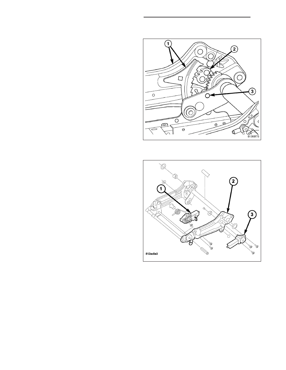
WARNING: A seat structure that has seen signifi-
cant load may have the locking mechanism acti-
vated and may exhibit the following symptoms:

Locking pawl (2) loose

Locking pawl (2) engaged into the seat frame
sidemember (1)

Height adjuster only works on outboard side

Broken or missing shear pin (3)

If any one or more of these symptoms exist
replace the height adjuster assembly. Do not
attempt

any

repairs.

Failure

to

follow

these

instructions may result in personal injury or death.

FRONT TILT MOTOR

1. Position motor (1) on seat adjuster (2).

8N - 194

POWER SEATS - SERVICE INFORMATION

LX

2. Install the fasteners (1) holding the motor to the

seat adjuster (2). Tighten the screws to 5 N·m (44
in. lbs.).

3. Connect the motor electrical connector.

4. Install the seat cushion (Refer to 23 - BODY/

SEATS/SEAT CUSHION

COVER

-

INSTALLA-

TION).

5. Clip the wire harness to cushion pan.

6. Install the seat assembly (Refer to 23 - BODY/

SEATS/SEAT - INSTALLATION).

7. Connect the battery negative cable.

8. Verify

normal

operation

of

the

power

seat

assembly.

LX

POWER SEATS - SERVICE INFORMATION

8N - 195

HEIGHT ADJUST MOTOR

1. Ensure the seat adjuster (2) is in the full up posi-

tion by pulling upward on the upper adjuster
assembly.

2. Position motor (3) on seat adjuster (2).

3. Install the motor shaft screw and washer and

tighten until snug. Do not torque screw at this
time.

4. Install the screws (1) holding the motor (3) to the

seat adjuster (2). It may be necessary to twist
the motor slightly to align the fastener holes.

5. Starting with the bottom screw, tighten the motor

screws (1) to 9 N·m (80 in. lbs.).

6.

Tighten the motor shaft screw and washer to 6.5

N·m (57.5 in. lbs.).

7. Connect the motor electrical connector.

8. Install the seat cushion (Refer to 23 - BODY/

SEATS/SEAT CUSHION

COVER

-

INSTALLA-

TION).

9. Clip the wire harness to cushion pan.

10. Install the seat assembly (Refer to 23 - BODY/

SEATS/SEAT - INSTALLATION).

11. Connect the battery negative cable.

12. Verify

normal

operation

of

the

power

seat

assembly.

8N - 196

POWER SEATS - SERVICE INFORMATION

LX

POWER SEAT RECLINER

REMOVAL

NOTE: The recliner motor is serviced as part of
the seat back frame. Do not attempt to transfer the
motor as the service part will come equipped with
a new motor installed.

1. Remove the seat back frame assembly (Refer to

23 - BODY/SEATS/SEAT BACK CUSHION/COVER
- REMOVAL).

2. Remove any parts that will need to be installed on

new seat back frame assembly.

INSTALLATION

1. Install parts from old seat back assembly as nec-

essary.

2. Install the seat back (1) (Refer to 23 - BODY/

SEATS/SEAT

BACK

CUSHION/COVER

-

INSTALLATION).

LX

POWER SEATS - SERVICE INFORMATION

8N - 197


Content   ..  622  623  624  625   ..