Chrysler 300/300 Touring/300C, Dodge Magnum. Manual - part 538


  Index      Chrysler     Chrysler 300/300 Touring/300C, Dodge Magnum - service repair manual


Search            


Content   ..  536  537  538  539   ..


Chrysler 300/300 Touring/300C, Dodge Magnum. Manual - part 538


When Monitored:
With the ignition switch on.

Set Condition:
The Multi-Purpose Module (Police And Taxi Interface Module-PTIM) has detected the Malfunction Indicator Sig-
nal circuit above a calibrated value.

Possible Causes

(W516) MALFUNCTION INDICATOR SIGNAL CIRCUIT OPEN OR SHORTED TO POWER

AFTERMARKET LIGHT/SIREN CONTROLLER

MULTI-PURPOSE MODULE (POLICE AND TAXI INTERFACE MODULE-PTIM)

1.

CHECK FOR ANY OF THE FOLLOWING ACTIVE DTCS

With the scan tool, read all active DTCs from all modules.

NOTE: Check for FCM configuration, CAN B or C hardware electrical, VIN Missing/Mismatch, battery or igni-
tion related DTCs.

Does the scan tool display any active DTCs to the conditions listed above?

Yes

>> Diagnose and repair the DTC. Refer to the Table of Contents in ELECTRONIC CONTROL MODULES -

ELECTRICAL DIAGNOSTICS for a complete list of the symptoms.

Perform BODY VERIFICATION TEST – VER 1. (Refer to BODY VERIFICATION TEST – VER 1).

No

>> Go To 2. Diagnostic Test

2.

CHECK FOR ACTIVE DTC

With the scan tool, read the active DTCs.

Erase the DTCs.

Turn the ignition off, wait 10 seconds, then turn the ignition on.

With the scan tool, read the active DTC’s.

Does the scan tool display this DTC as active?

Yes

>> Go To 3.

No

>> If the DTC is stored, check for an intermittent condition. Visually inspect the related wiring harness con-

nectors. Look for broken, bent, pushed out, or corroded terminals, and repair any obvious problems.

Perform BODY VERIFICATION TEST – VER 1. (Refer to BODY VERIFICATION TEST – VER 1).

3.

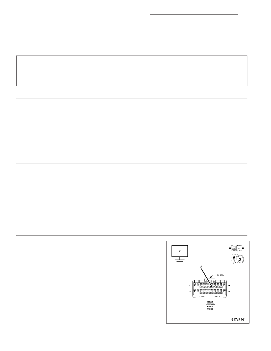
CHECK THE (W516) MALFUNCTION INDICATOR SIGNAL CIRCUIT FOR A SHORT TO POWER

Turn the ignition off.

Disconnect the Multi-Purpose Module (Police And Taxi Interface Mod-
ule-PTIM) C2 harness connector.

Turn the ignition on.

Measure the voltage of the (W516) Malfunction Indicator Signal circuit
between ground and the Multi-Purpose Module (Police And Taxi Inter-
face Module-PTIM) C2 harness connector.

Is there any voltage present?

Yes

>> Go To 4.

No

>> Go To 5.

8M - 22

MESSAGE CENTER - ELECTRICAL DIAGNOSTICS

LX

4.

ISOLATE THE SHORT TO VOLTAGE IN THE (W516) MALFUNCTION INDICATOR SIGNAL CIRCUIT

Turn the ignition off.

Disconnect the Multi-Purpose Module (Police And Taxi Interface Mod-
ule-PTIM) 24 way harness connector (aftermarket light/siren controller
side).

Turn the ignition on.

Measure the voltage of the (W516) Malfunction Indicator Signal circuit
between ground and the Multi-Purpose Module (Police And Taxi Inter-
face Module-PTIM) C2 harness connector.

Is there any voltage present?

Yes

>> Repair the (W516) Malfunction Indicator Signal circuit for a

short to power.

Perform BODY VERIFICATION TEST – VER 1. (Refer to
BODY VERIFICATION TEST – VER 1).

No

>> Refer to electrical diagnostics for the aftermarket light/siren

controller, and repair or replace the aftermarket light siren
controller in accordance with the manufacturer’s service
information.

Perform BODY VERIFICATION TEST – VER 1. (Refer to BODY VERIFICATION TEST – VER 1).

5.

CHECK THE (W516) MALFUNCTION INDICATOR SIGNAL CIRCUIT FOR AN OPEN

Turn the ignition off.

Disconnect the Multi-Purpose Module (Police And Taxi Interface Mod-
ule-PTIM) 24 way harness connector (aftermarket light/siren controller
side).

Measure the resistance of the (W516) Malfunction Indicator Signal cir-
cuit between the Multi-Purpose Module (Police And Taxi Interface Mod-
ule-PTIM) 24 way and the Multi-Purpose Module (Police And Taxi
Interface Module-PTIM) C2 harness connectors.

Is the resistance below 5.0 ohms?

Yes

>> Go To 6.

No

>> Repair the (W516) Malfunction Indicator Signal circuit for an

open or high resistance.

Perform BODY VERIFICATION TEST – VER 1. (Refer to
BODY VERIFICATION TEST – VER 1).

LX

MESSAGE CENTER - ELECTRICAL DIAGNOSTICS

8M - 23

6.

CHECK THE MULTI-PURPOSE MODULE (POLICE AND TAXI INTERFACE MODULE-PTIM)

Turn the ignition off.

Disconnect all Multi-Purpose Module (Police And Taxi Interface Module-PTIM) and aftermarket light/siren controller
harness connectors.

Check for damaged or corroded pins, pinched wires, or damaged connectors, and repair any obvious problems.

Connect all Multi-Purpose Module (Police And Taxi Interface Module-PTIM) and aftermarket light/siren controller har-
ness connectors.

Turn the ignition on.

With the scan tool monitor active codes as you work through the following step.

Wiggle the wiring harness and connectors of the Multi-Purpose Module (Police And Taxi Interface Module-PTIM) and
aftermarket light/siren controller.

If only stored codes return continue the test until the problem area has been isolated, and repair any obvious prob-
lems.

Is DTC P164B — MIL OUTPUT CIRCUIT HIGH still displayed?

Yes

>> Replace the Multi-Purpose Module (Police And Taxi Interface Module-PTIM) in accordance with the ser-

vice information.

Perform BODY VERIFICATION TEST – VER 1. (Refer to BODY VERIFICATION TEST – VER 1).

No

>> Repair is complete. The problem may have been caused by a loose or corroded terminal.

Perform BODY VERIFICATION TEST – VER 1. (Refer to BODY VERIFICATION TEST – VER 1).

8M - 24

MESSAGE CENTER - ELECTRICAL DIAGNOSTICS

LX

P170A — PARK/NEUTRAL OUTPUT CIRCUIT LOW

For a complete wiring diagram Refer to Section 8W.

LX

MESSAGE CENTER - ELECTRICAL DIAGNOSTICS

8M - 25


Content   ..  536  537  538  539   ..