Chrysler 300/300 Touring/300C, Dodge Magnum. Manual - part 481


  Index      Chrysler     Chrysler 300/300 Touring/300C, Dodge Magnum - service repair manual


Search            


Content   ..  479  480  481  482   ..


Chrysler 300/300 Touring/300C, Dodge Magnum. Manual - part 481


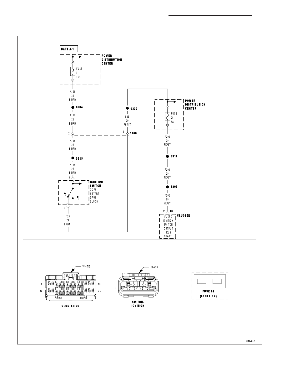
B2107-IGNITION SWITCH SENSE INPUT CIRCUIT/PERFORMANCE

For a complete wiring diagram Refer to Section 8W.

8J - 28

INSTRUMENT CLUSTER - ELECTRICAL DIAGNOSTICS

LX

When Monitored:
With the Instrument Cluster awake.

Set Condition:
Ignition switch in RUN or START, and Ignition RUN/START LOW. Ignition Switch in LOCK or UNLOCK, and
Ignition RUN/START HIGH.

Possible Causes

FUSED IGNITION SWITCH FUSES

(F202) FUSED IGNITION SWITCH OUTPUT (RUN-START) OPEN

(A106) FUSED B+ CIRCUIT OPEN

IGNITION SWITCH

INSTRUMENT CLUSTER

Diagnostic Test

1.

CHECK FOR AN ACTIVE DTC

Turn the ignition on.

With the scan tool, record and erase DTCs.

Wait 30 seconds.

With the scan tool, read DTCs.

Is the DTC active?

Yes

>> Go To 2

No

>> The condition that caused this code to set is not present at this time. Check for an intermittent condition

by inspecting the related wiring harness for chafed, pierced, pinched, and partially broken wires. Also
inspect the related connectors for broken, bent, pushed out, spread, corroded, or contaminated termi-
nals.

Perform BODY VERIFICATION TEST - VER 1. (Refer to BODY VERIFICATION TEST - VER 1).

2.

CHECK PDC FUSES

Inspect PDC fuses #8, and #29 in the PDC.

Is either fuse open?

Yes

>> Using the wiring diagram/schematic as a guide, inspect the wiring and connectors for a short to ground

condition.

Perform BODY VERIFICATION TEST - VER 1. (Refer to BODY VERIFICATION TEST - VER 1).

No

>> Go To 3

LX

INSTRUMENT CLUSTER - ELECTRICAL DIAGNOSTICS

8J - 29

3.

CHECK FOR VOLTAGE ON THE (F202) FUSED IGNITION SWITCH OUTPUT (RUN-START) CIRCUIT

Turn the ignition off.

Disconnect the Instrument Cluster C3 harness connector.

Turn the ignition on.

Measure the voltage of the (F202) Fused Ignition Switch Output (Run-
Start) circuit.

Is the voltage above 10.0 volts?

Yes

>> Replace the Instrument Cluster in accordance with the ser-

vice information.

Perform BODY VERIFICATION TEST - VER 1. (Refer to
BODY VERIFICATION TEST - VER 1).

No

>> Go To 4

4.

CHECK THE (F202, F20) FUSED IGNITION SWITCH OUTPUT (RUN-START) CIRCUIT FOR AN OPEN

Disconnect the Ignition Switch harness connector.

Measure the resistance of the (F202, F20) Fused Ignition Switch Output
(Run-Start) circuit between the Instrument Cluster C3 harness connec-
tor and the Ignition Switch harness connector.

Is the resistance above 5.0 ohms?

Yes

>> Repair the (F202, F20) Fused Ignition Switch Output (Run-

Start) circuit for an open.

Perform BODY VERIFICATION TEST - VER 1. (Refer to
BODY VERIFICATION TEST - VER 1).

No

>> Go To 5

8J - 30

INSTRUMENT CLUSTER - ELECTRICAL DIAGNOSTICS

LX

5.

CHECK THE (A106) FUSED B+ CIRCUIT FOR AN OPEN

Measure the voltage on the (A106) Fused B+ circuit at the Ignition
Switch harness connector.

Is the voltage above 10.0 volts?

Yes

>> Replace the Ignition Switch in accordance with the service

information.

Perform BODY VERIFICATION TEST - VER 1. (Refer to
BODY VERIFICATION TEST - VER 1).

No

>> Repair the (A106) Fused B+ circuit for an open.

Perform BODY VERIFICATION TEST - VER 1. (Refer to
BODY VERIFICATION TEST - VER 1).

LX

INSTRUMENT CLUSTER - ELECTRICAL DIAGNOSTICS

8J - 31


Content   ..  479  480  481  482   ..