Chrysler 300/300 Touring/300C, Dodge Magnum. Manual - part 472


  Index      Chrysler     Chrysler 300/300 Touring/300C, Dodge Magnum - service repair manual


Search            


Content   ..  470  471  472  473   ..


Chrysler 300/300 Touring/300C, Dodge Magnum. Manual - part 472


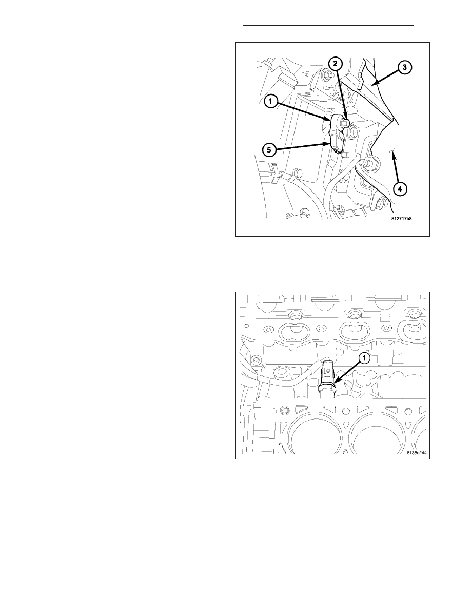
3. Disconnect knock sensor electrical connector (5).

4. Remove sensor mounting bolt (2). Note foam strip

on bolt threads. This foam is used only to retain the
bolts to sensors for plant assembly. It is not used
as a sealant. Do not apply any adhesive, sealant or
thread locking compound to these bolts.

5. Remove sensor from engine.

INSTALLATION

2.7L

The sensors screws into the cylinder block, directly
below the intake manifold.

1. Install knock sensor. Tighten knock sensor to 10

N·m (7 ft. lbs.) torque. Over or under tightening
effects knock sensor performance resulting in
possible improper spark control.

2. Attach electrical connector to knock sensor.

3.

Install the passenger side cylinder head, (Refer to

9 - ENGINE/CYLINDER HEAD - INSTALLATION)

4. Install intake manifold, (Refer to 9 - ENGINE/MAN-

IFOLDS/INTAKE MANIFOLD - INSTALLATION)

5. connect negative battery cable.

8I - 66

IGNITION SYSTEM - SERVICE INFORMATION

LX

3.5L

1. Install knock sensor. Tighten knock sensor to 20

N·m (15.2 in. lbs.) torque. Over or under tighten-
ing effects knock sensor performance, possibly
causing improper spark control.

2. Route the knock sensor wire in the proper location.

3. Install the intake manifold, (Refer to 9 - ENGINE/

MANIFOLDS/INTAKE

MANIFOLD

-

INSTALLA-

TION)

LX

IGNITION SYSTEM - SERVICE INFORMATION

8I - 67

4. Connect electrical connector.

5. Connect negative battery cable.

5.7L

1. Thoroughly clean knock sensor mounting hole.

2. Install sensor (1) into cylinder block.

NOTE: Over or under tightening the sensor mount-
ing bolts will affect knock sensor performance,
possibly causing improper spark control. Always
use the specified torque when installing the knock
sensors. The torque for the knock senor bolt is
relatively light for an 8mm bolt.

NOTE: Note foam strip on bolt threads. This foam
is used only to retain the bolts to sensors for
plant assembly. It is not used as a sealant. Do not
apply any adhesive, sealant or thread locking
compound to these bolts.

3. Install and tighten mounting bolt (2). Refer to

torque specification.

4. Install electrical connector to sensor.

8I - 68

IGNITION SYSTEM - SERVICE INFORMATION

LX

6.1L

1. Thoroughly clean knock sensor mounting hole.

2. Install sensor (1) onto cylinder block.

NOTE: Over or under tightening the sensor mount-
ing bolts will affect knock sensor performance,
possibly causing improper spark control. Always
use the specified torque when installing the knock
sensors. The torque for the knock senor bolt is
relatively light for an 8mm bolt.

NOTE: Note foam strip on bolt threads. This foam
is used only to retain the bolts to sensors for
plant assembly. It is not used as a sealant. Do not
apply any adhesive, sealant or thread locking
compound to these bolts.

3. Install and tighten mounting bolt (2). Refer to

torque specification.

4. Install electrical connector (5) to sensor.

5. Install heat shield (1) to sensor (shield snaps on).

LX

IGNITION SYSTEM - SERVICE INFORMATION

8I - 69


Content   ..  470  471  472  473   ..