Chrysler 300/300 Touring/300C, Dodge Magnum. Manual - part 430


  Index      Chrysler     Chrysler 300/300 Touring/300C, Dodge Magnum - service repair manual


Search            


Content   ..  428  429  430  431   ..


Chrysler 300/300 Touring/300C, Dodge Magnum. Manual - part 430


HEATED GLASS - SERVICE INFORMATION

DESCRIPTION

CAUTION: Grid lines can be damaged or scraped off with sharp instruments. Care should be taken in clean-
ing glass or removing foreign materials, decals or stickers. Normal glass cleaning solvents or hot water
used with rags or toweling is recommended.

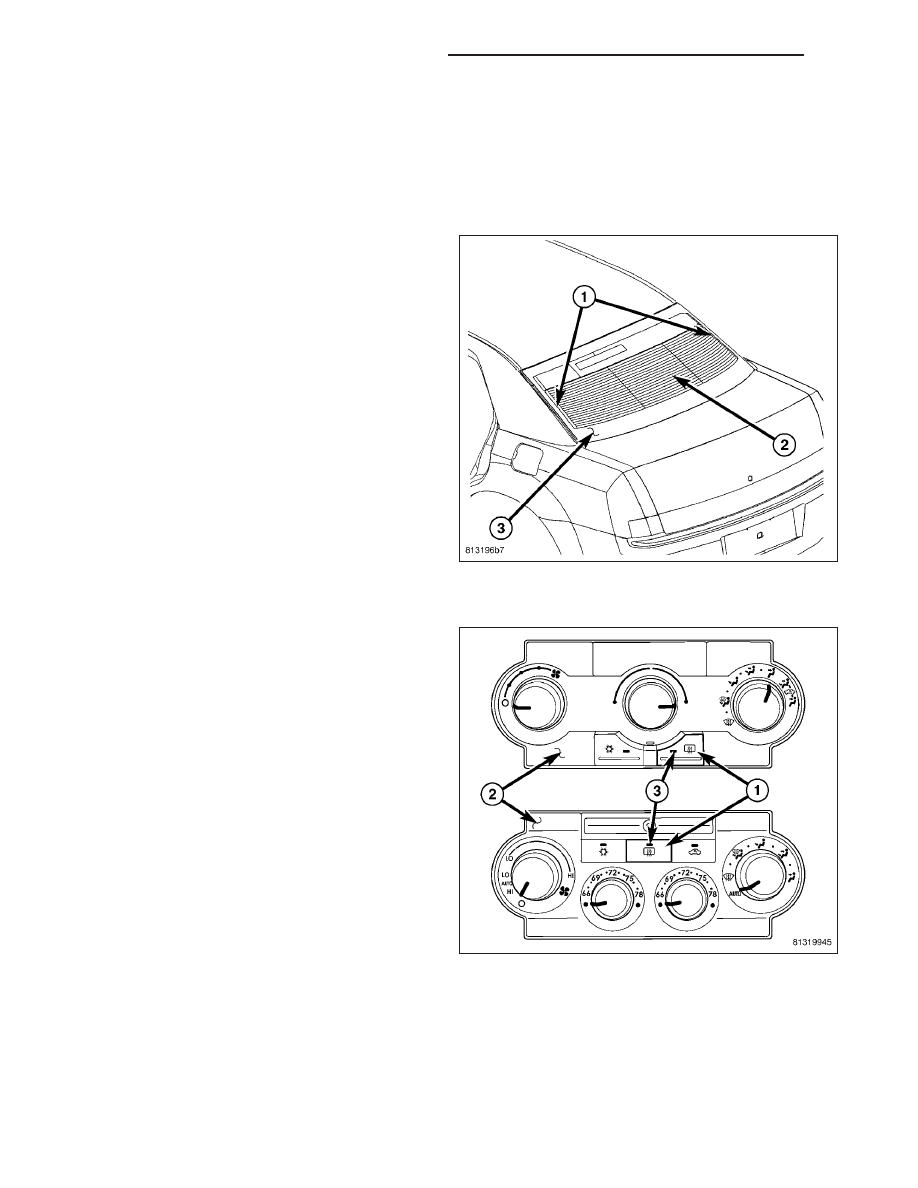
The rear window defogger system, also known as
electric backlight (EBL), consists of two vertical bus
bars (1) linked by a series of grid lines (2) fired onto
the inside surface of the rear window (3).

The EBL system is turned On or Off by a switch and
timing circuit integral to the A/C-heater control located
at the center of the instrument panel.

Circuit protection is provided by two cartridge fuses
located in the power distribution center (PDC). One
fuse is for the heated rear window grid circuit and the
other fuse is for the heated outside mirror grid circuit,
when equipped.

OPERATION

The electric backlight (EBL) system is controlled by a
momentary switch (1) located in the A/C-heater control
(2) on the instrument panel. When the rear window
defogger switch is pressed to the On position, the
A/C-heater control energizes the rear window defog-
ger (EBL) relay and battery current is then directed
through the relay and to the rear window defogger grid
lines and the heated outside rear view mirrors, when
equipped. The grid lines heat the glass to help clear
the rear window and outside mirror surfaces of fog or
frost.

An amber indicator (3) in the rear window defogger
switch will illuminate to indicate when the EBL system
is turned on. The A/C-heater control contains the EBL
system control circuitry including the timer logic.

NOTE: The EBL system turns off automatically
after ten minutes of initial operation. Each follow-
ing activation cycle of the EBL system will last five
minutes.

The EBL system will be automatically turned off after an initial programmed time interval of about ten minutes. After
the initial time interval has expired, if the rear window defogger switch is turned on again during the same ignition
cycle, the EBL system will automatically turn off after about five minutes. The EBL system will automatically shut off
if the ignition switch is turned to the Off position, or it can be turned off manually by pressing the rear window
defogger switch a second time.

Repair of the rear window defogger grid lines, bus bars, terminals or pigtail wires can be accomplished using the
Mopar Rear Window Defogger Repair Kit (Part Number 04549275) or equivalent (Refer to 8 - ELECTRICAL/

8G - 2

HEATED GLASS - SERVICE INFORMATION

LX

HEATED GLASS/REAR WINDOW DEFOGGER GRID - STANDARD PROCEDURE - GRID LINE AND TERMINAL
REPAIR).

DIAGNOSIS AND TESTING

ELECTRIC BACKLIGHT (EBL) SYSTEM

NOTE: Illumination of the defogger switch indicator lamp does not necessary mean that electrical current is
reaching the rear glass heating grid lines.

NOTE: For circuit descriptions and diagrams of the rear window defogger system, refer to 8W - WIRING
DIAGRAM INFORMATION.

Operation of the electric backlight (EBL) system can be confirmed by the following:

1.

If equipped with the automatic temperature control

(ATC) heating-A/C system, use a scan tool and
check for diagnostic trouble codes (DTCs) related
to the A/C-heater control. If equipped with the man-
ual temperature control (MTC) heating-A/C system,
use the A/C-heater control to check for diagnostic
trouble codes (DTCs) related to the A/C-heater
control (Refer to 24 - HEATING & AIR CONDI-
TIONING - DIAGNOSIS AND TESTING - HVAC
SELF DIAGNOSTICS). If no DTCs are found, go to
Step 2. If any DTCs are found, repair as required,
then proceed to Step 2

2. Turn the ignition switch to the On position. Set the

rear window defogger switch in the On position.
The rear window defogger operation can be
checked by feeling the rear window or outside rear
view mirror glass surfaces. A distinct difference in temperature between the grid lines (4 and 5) and the adjacent
clear glass or the mirror glass should be detected within three to four minutes of operation.

3. If a temperature difference is not detected, use a 12-volt DC voltmeter and contact the rear glass heating grid

terminal A (1) with the negative lead, and terminal B (2) with the positive lead. The voltmeter should read battery
voltage. If the voltmeter does not read battery voltage, check the following:

Confirm that the ignition switch is in the On position.

Make sure that the rear glass heating grid feed wire (3) and ground wire (6) are connected to the terminals.
Confirm that the ground wire has continuity to ground.

Check the EBL relay and fuses located in the power distribution center (PDC) in the engine compartment. The
relay and fuses must be tight in their receptacles and all electrical connections must be secure.

When the above steps have been completed and the rear glass heating grid is still inoperative, one or more of the
following is faulty:

Rear window defogger switch in the A/C-heater control.

Rear window defogger grid lines (all grid lines would have to be broken, or the power feed or the ground wire
disconnected, for the entire heating grid to be inoperative).

4. If the EBL system operation has been verified but the rear window defogger LED indicator does not illuminate,

replace the A/C-heater control (Refer to 24 - HEATING & AIR CONDITIONING/CONTROLS/CONTROL-A/C
HEATER - REMOVAL).

LX

HEATED GLASS - SERVICE INFORMATION

8G - 3

GRID-REAR WINDOW DEFOGGER

STANDARD PROCEDURE

GRID LINE AND TERMINAL REPAIR

WARNING: Materials contained in the Repair Kit (Part Number 04549275) may cause skin or eye irritation.
The kit contains epoxy resin and amine type hardener, which are harmful if swallowed. Avoid contact with
the skin and eyes. For skin contact, wash the affected areas with soap and water. For contact with the eyes,
flush with plenty of water. Do not take internally. If taken internally, induce vomiting and call a physician
immediately. Use with adequate ventilation. Do not use near fire or flame. Contains flammable solvents.
Keep out of the reach of children. Failure to follow the warnings could result in possible personal injury or
death.

Repair of the rear glass heating grid lines, bus bars, terminals or pigtail wires can be accomplished using the Mopar
Rear Window Defogger Repair Kit (Part Number 04549275) or equivalent.

1. Mask the repair area with masking tape (3) so that

the conductive epoxy can be applied neatly. Extend
the epoxy application onto the grid line (2) or the
bus bar on each side of the break (1).

2. Follow the instructions in the repair kit for preparing

the damaged area.

3. Remove the package separator clamp and mix the

two

conductive

epoxy

components

thoroughly

within the packaging. Fold the package in half and
cut the center corner to dispense the epoxy.

4. For grid line repairs, mask the area to be repaired

with masking tape or use a template.

5. Apply the epoxy through the slit in the masking

tape or template. Overlap both ends of the break
by at least 19 millimeters (0.75 inch).

6. For a terminal or pigtail wire replacement, mask the adjacent areas so the epoxy can be extended onto the

adjacent grid line as well as the bus bar. Apply a thin layer of epoxy to the area where the terminal or pigtail wire
was fastened and onto the adjacent grid line.

7. Apply a thin layer of conductive epoxy to the terminal or bare wire end of the pigtail and place it in the proper

location on the bus bar. To prevent the terminal or pigtail wire from moving while the epoxy is curing, it must be
wedged or clamped.

8. Carefully remove the masking tape or template.

CAUTION: Do not allow the glass surface to exceed 204° C (400° F) when using a heat gun, or the glass
may fracture.

9. Allow the epoxy to cure 24 hours at room temperature, or carefully use a heat gun for fifteen minutes. When

using a heat gun, hold it approximately 25.4 centimeters (10 inches) from the repair and do not allow the glass
surface to exceed 204° C (400° F).

10. After the conductive epoxy is properly cured, remove the wedge or clamp from the terminal or pigtail wire.

11. Connect the wire harness leads to the grid terminals or pigtail wires and verify EBL operation.

8G - 4

HEATED GLASS - SERVICE INFORMATION

LX

RELAY-REAR WINDOW DEFOGGER

DESCRIPTION

The rear window defogger (EBL) relay (1) is a Inter-
national

Standards

Organization

(ISO)-type

relay.

Relays conforming to the ISO specifications have
common physical dimensions, current capacities, ter-
minal functions and patterns (2). The EBL relay is a
electromechanical device that switches battery current
through a fuse in the power distribution center (PDC)
to the rear window defogger grid and when equipped,
switches battery current through a fuse in the PDC to
the heated outside rear view mirrors. The EBL relay is
energized when the relay coil is provided a ground
path by the control circuitry within the A/C-heater con-
trol.

The EBL relay is located in the PDC at the rear of the
vehicle, near the battery.

OPERATION

The ISO-standard rear window defogger (EBL) micro-relay is an electromechanical switch that uses a low current
input controlled by the A/C-heater control to control the high current output to the rear window defogger grid lines.
The movable, common feed relay contact is held against the fixed, normally closed relay contact by spring pressure.
When the electromagnetic relay coil is energized, it draws the movable common feed relay contact away from the
fixed, normally closed relay contact and, holds it against the fixed, normally open relay contact. This action allows
high current to flow to the rear window defogger grid lines.

When the relay coil is de-energized, spring pressure returns the movable relay contact back against the fixed, nor-
mally closed contact point. The resistor or diode is connected in parallel with the relay coil, and helps to dissipate
voltage spikes and electromagnetic interference that can be generated as the electromagnetic field of the relay coil
collapses.

The EBL relay terminals are connected to the vehicle electrical system through a receptacle in the power distribution
center (PDC). The inputs and outputs of the EBL relay include:

The common feed terminal (30) receives a battery current input from a fused B(+) circuit at all times.

The coil ground terminal (85) receives a ground through the EBL relay control circuit only when the A/C-heater
control electronically pulls the circuit to ground.

The coil battery terminal (86) receives a battery current input from a fused B(+) circuit at all times.

The normally open terminal (87) provides battery current to the rear window defogger grid through the EBL
relay output circuit and a fuse located in the PDC only when the EBL relay coil is energized.

The normally closed terminal (87A) is not connected to any circuit in this application, but provides a battery
current output only when the EBL relay coil is de-energized.

The EBL micro-relay cannot be repaired and, if faulty or damaged, it must be replaced. Refer to the appropriate
wiring information for diagnosis and testing of the ISO-standard micro-relay and for complete rear window defogger
(EBL) wiring diagrams.

LX

HEATED GLASS - SERVICE INFORMATION

8G - 5


Content   ..  428  429  430  431   ..