Chrysler 300/300 Touring/300C, Dodge Magnum. Manual - part 376


  Index      Chrysler     Chrysler 300/300 Touring/300C, Dodge Magnum - service repair manual


Search            


Content   ..  374  375  376  377   ..


Chrysler 300/300 Touring/300C, Dodge Magnum. Manual - part 376


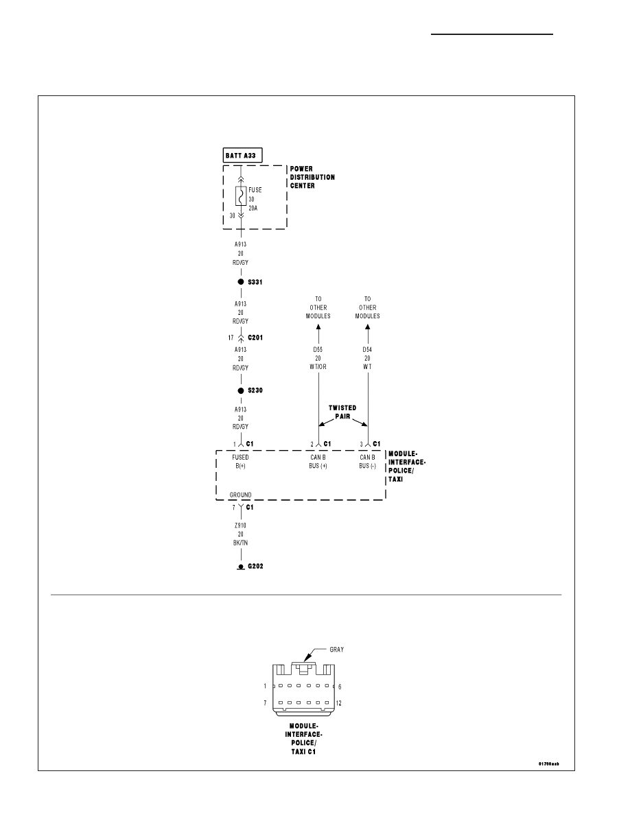
*NO RESPONSE FROM MULTI-PURPOSE MODULE (POLICE AND TAXI INTERFACE
MODULE-PTIM)

8E - 194

ELECTRONIC CONTROL MODULES - ELECTRICAL DIAGNOSTICS

LX

For a complete wiring diagram Refer to Section 8W.

Possible Causes

(A913) FUSED B (+) CIRCUIT OPEN OR SHORTED

(Z910) GROUND CIRCUIT OPEN

(D55) AND (D54) CAN B BUS CIRCUITS OPEN

MULTI-PURPOSE MODULE (POLICE AND TAXI INTERFACE MODULE-PTIM)

Diagnostic Test

1.

TEST FOR INTERMITTENT CONDITION

Turn the ignition on.

NOTE: Ensure the IOD fuse is installed and battery voltage is between 10.0 and 16.0 volts.
With the scan tool, select ECU View.

NOTE: A red X will be next to the module that is not communicating, indicating that the module is not active
on the Bus network. A green check indicates that the module is active on the Bus network.

Does the scan tool display a red X next to the module?

Yes

>> Go To 2

No

>> The no response condition is not present at this time. Using the wiring diagram/schematic as a guide,

inspect the wiring for chafed, pierced, pinched, and partially broken wires and the wiring harness con-
nectors for broken, bent, pushed out, and corroded terminals.

2.

(A913) FUSED B(+) CIRCUIT OPEN OR SHORTED

Turn the ignition off.

Disconnect the C1 Multi-Purpose Module (Police And Taxi Interface
Module-PTIM) harness connector.

Using a 12-volt test light connected to ground, check the (A913) Fused
B(+) circuit.

Does the test light illuminate brightly?

Yes

>> Go To 3

No

>> Repair the (A913) Fused B(+) circuit for an open or short.

Perform BODY VERIFICATION TEST – VER 1. (Refer to
BODY VERIFICATION TEST – VER 1).

LX

ELECTRONIC CONTROL MODULES - ELECTRICAL DIAGNOSTICS

8E - 195

3.

(Z910) GROUND CIRCUIT OPEN

Using a 12-volt test light connected to 12-volts, check the (Z910)
ground circuit.

Does the test light illuminate brightly?

Yes

>> Go To 4

No

>> Repair the (Z910) ground circuit for an open.

Perform BODY VERIFICATION TEST – VER 1. (Refer to
BODY VERIFICATION TEST – VER 1).

4.

(D55) AND (D54) CAN B BUS CIRCUITS OPEN

NOTE: One open circuit will not cause this condition.
Measure the voltage between the (D54) CAN B Bus (-) circuit and
ground.

Measure the voltage between the (D55) CAN B Bus (+) circuit and
ground.

Is there any voltage present on either circuit?

Yes

>> Replace the Multi-Purpose Module (Police And Taxi Inter-

face Module-PTIM) in accordance with the service informa-
tion.

Perform BODY VERIFICATION TEST – VER 1. (Refer to
BODY VERIFICATION TEST – VER 1).

No

>> Repair the (D55) and (D54) CAN B Bus circuits for an open.

Inspect the connector for damage.

Perform BODY VERIFICATION TEST – VER 1. (Refer to
BODY VERIFICATION TEST – VER 1).

8E - 196

ELECTRONIC CONTROL MODULES - ELECTRICAL DIAGNOSTICS

LX

*NO RESPONSE FROM MSMD (MEMORY SEAT MODULE)

For a complete wiring diagram Refer to Section 8W.

LX

ELECTRONIC CONTROL MODULES - ELECTRICAL DIAGNOSTICS

8E - 197


Content   ..  374  375  376  377   ..