Chrysler 300/300 Touring/300C, Dodge Magnum. Manual - part 2350


  Index      Chrysler     Chrysler 300/300 Touring/300C, Dodge Magnum - service repair manual


Search            


Content   ..  2348  2349  2350  2351   ..


Chrysler 300/300 Touring/300C, Dodge Magnum. Manual - part 2350


NOTE: If an internal failure of the A/C compressor has occurred, the receiver/drier must be replaced.

1. Recover the refrigerant from the refrigerant system

(Refer to 24 - HEATING & AIR CONDITIONING/
PLUMBING

-

STANDARD

PROCEDURE

-

REFRIGERANT SYSTEM RECOVERY).

2. Disconnect and isolate the negative battery cable.

3. Remove the air cleaner housing (Refer to 9 -

ENGINE/AIR

INTAKE

SYSTEM/AIR

CLEANER

HOUSING - REMOVAL).

4. Remove the accessory drive belt (Refer to 7 -

COOLING/ACCESSORY

DRIVE/BELTS-DRIVE

-

REMOVAL).

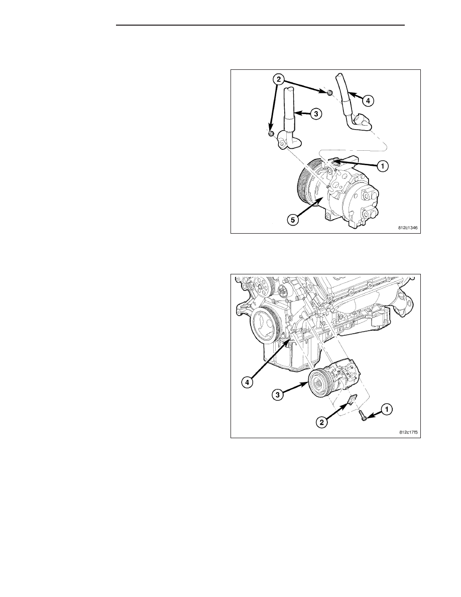
5. Disconnect the engine wire harness from the com-

pressor clutch field coil connector (1).

6. Remove the nuts (2) that secure the A/C suction

line (3) and A/C discharge line (4) to the A/C com-
pressor (5).

7. Disconnect the suction and discharge lines from

the A/C compressor and remove and discard the
dual plane seals.

8. Install plugs in, or tape over all of the opened refrigerant line fittings and the compressor ports.

NOTE: 5.7L engine shown in illustration. 6.1L sim-
ilar.

9. Raise and support the vehicle.

10. Remove the front end splash shield (Refer to 23 -

BODY/EXTERIOR/FRONT

END

SPLASH

SHIELDS - REMOVAL).

11. Support the A/C compressor (3) and remove the

bolts (1) that secure the automatic transmission
cooler line bracket (2) and the compressor to the
cylinder block (4).

12. Position the cooler lines out of the way and

remove the A/C compressor from the engine
compartment.

INSTALLATION

2.7L ENGINE

NOTE: Be certain to check the refrigerant oil level if the A/C compressor is being replaced (Refer to 24 -
HEATING & AIR CONDITIONING/PLUMBING/REFRIGERANT OIL - STANDARD PROCEDURE - REFRIGERANT
OIL LEVEL). Use only refrigerant oil of the type recommended for the A/C compressor in the vehicle.

NOTE: If an internal failure of the A/C compressor has occurred, the receiver/drier must be replaced.

24 - 434

PLUMBING

LX

CAUTION: Use care not to deform or damage the
automatic transmission cooler lines and retaining
bracket when repositioning the A/C compressor.

NOTE: The bolt that secures the transmission
cooler line bracket to the A/C compressor must be
installed through the bracket and the lower front
mounting hole of the compressor prior to final
positioning of the compressor to the cylinder
block.

1. Loosely install the bolt (3) that secures the auto-

matic transmission cooler line bracket (4) to the
A/C compressor (5) and position the compressor,
bracket and bolt to the cylinder block (6).

2. Loosely install the bolts (1 and 2) that secure the

A/C compressor to the cylinder block.

3. Tighten the three bolts in the following order:

1. Upper front bolt to 26 N·m (19 ft. lbs.).

2. Lower front bolt to 26 N·m (19 ft. lbs.).

3. Rear bolt to 50 N·m (37 ft. lbs.).

4. Install the front end splash shields (Refer to 23 - BODY/EXTERIOR/FRONT END SPLASH SHIELDS - INSTAL-

LATION).

5. Lower the vehicle.

6. Remove the tape or plugs from the opened fittings

on the A/C suction line (3) and the A/C discharge
line (4) and the compressor ports.

7. Lubricate the new dual plane seals with clean

refrigerant oil and install them onto the suction and
the discharge line fittings. Use only the specified
seals as they are made of a special material for the
R-134a system. Use only refrigerant oil of the type
recommended for the A/C compressor in the vehi-
cle.

8. Connect the suction and discharge lines onto the

A/C compressor (5).

9. Install the nuts (2) that secure the suction and dis-

charge lines to the A/C compressor. Tighten the
nuts to 23 N·m (17 ft. lbs.).

10. Connect the engine wire harness to the compres-

sor clutch field coil connector (1).

11. Install the accessory drive belt (Refer to 7 -

COOLING/ACCESSORY DRIVE/BELTS-DRIVE -
INSTALLATION).

12. Replace the receiver/drier if the A/C compressor is being replaced due to an internal failure (Refer to 24 -

HEATING & AIR CONDITIONING/PLUMBING/RECEIVER/DRIER - REMOVAL) and (Refer to 24 - HEATING &
AIR CONDITIONING/PLUMBING/RECEIVER/DRIER - INSTALLATION).

13. Install the air cleaner housing (Refer to 9 - ENGINE/AIR INTAKE SYSTEM/AIR CLEANER HOUSING - INSTAL-

LATION).

14. Reconnect the negative battery cable.

15. Evacuate the refrigerant system (Refer to 24 - HEATING & AIR CONDITIONING/PLUMBING - STANDARD

PROCEDURE - REFRIGERANT SYSTEM EVACUATE).

16. Charge the refrigerant system (Refer to 24 - HEATING & AIR CONDITIONING/PLUMBING - STANDARD PRO-

CEDURE - REFRIGERANT SYSTEM CHARGE).

LX

PLUMBING

24 - 435

3.0L ENGINE

NOTE: Be certain to check the refrigerant oil level if the A/C compressor is being replaced (Refer to 24 -
HEATING & AIR CONDITIONING/PLUMBING/REFRIGERANT OIL - STANDARD PROCEDURE - REFRIGERANT
OIL LEVEL). Use only refrigerant oil of the type recommended for the A/C compressor in the vehicle.

NOTE: If an internal failure of the A/C compressor has occurred, the receiver/drier must be replaced.

1. Position the A/C compressor (4) into the engine

compartment.

2. Loosely install the three bolts (1 and 2) that secure

the A/C compressor and the automatic transmis-
sion cooler line bracket to the cylinder block (5).

3. Tighten the three bolts in the following order to 26

N·m (19 ft. lbs.):

1. Upper front bolt.

2. Lower front bolt.

3. Rear bolt.

4. Install the front end splash shields (Refer to 23 -

BODY/EXTERIOR/FRONT

END

SPLASH

SHIELDS - INSTALLATION).

5. Lower the vehicle.

6. Remove the tape or plugs from the opened fittings

on the A/C suction line (3) and the A/C discharge
line (4) and the compressor ports.

7. Lubricate new dual plane seals with clean refriger-

ant oil and install them onto the suction and the
discharge line fittings. Use only the specified seals
as they are made of a special material for the
R-134a system. Use only refrigerant oil of the type
recommended for the A/C compressor in the vehi-
cle.

8. Connect the suction and discharge lines onto the

A/C compressor (5).

9. Install the nuts (2) that secure the suction and dis-

charge lines to the A/C compressor. Tighten the
nuts to 23 N·m (17 ft. lbs.).

10. Connect the engine wire harness to the compres-

sor clutch field coil connector (1).

11. Install the accessory drive belt (Refer to 7 -

COOLING/ACCESSORY DRIVE/BELTS-DRIVE -
INSTALLATION).

12. Replace the receiver/drier if the A/C compressor is being replaced due to an internal failure (Refer to 24 -

HEATING & AIR CONDITIONING/PLUMBING/RECEIVER/DRIER - REMOVAL) and (Refer to 24 - HEATING &
AIR CONDITIONING/PLUMBING/RECEIVER/DRIER - INSTALLATION).

13. Install the air cleaner housing (Refer to 9 - ENGINE/AIR INTAKE SYSTEM/AIR CLEANER HOUSING - INSTAL-

LATION).

14. Reconnect the negative battery cable.

15. Evacuate the refrigerant system (Refer to 24 - HEATING & AIR CONDITIONING/PLUMBING - STANDARD

PROCEDURE - REFRIGERANT SYSTEM EVACUATE).

24 - 436

PLUMBING

LX

16. Charge the refrigerant system (Refer to 24 - HEATING & AIR CONDITIONING/PLUMBING - STANDARD PRO-

CEDURE - REFRIGERANT SYSTEM CHARGE).

3.5L ENGINE

NOTE: Be certain to check the refrigerant oil level if the A/C compressor is being replaced (Refer to 24 -
HEATING & AIR CONDITIONING/PLUMBING/REFRIGERANT OIL - STANDARD PROCEDURE - REFRIGERANT
OIL LEVEL). Use only refrigerant oil of the type recommended for the A/C compressor in the vehicle.

NOTE: If an internal failure of the A/C compressor has occurred, the receiver/drier must be replaced.

CAUTION: Use care not to deform or damage the
automatic transmission cooler lines and retaining
bracket when repositioning the A/C compressor.

NOTE: The bolt that secures the transmission
cooler line bracket to the A/C compressor must be
installed through the bracket and the lower front
mounting hole of the compressor prior to final
positioning of the compressor to the cylinder
block.

1. Loosely install the bolt (3) that secures the auto-

matic transmission cooler line bracket (4) to the
A/C compressor (5) and position the compressor,
bracket and bolt to the cylinder block (6).

2. Loosely install the bolts (1 and 2) that secure the

A/C compressor to the cylinder block.

3. Tighten all three bolts that secure the A/C compres-

sor to the engine in the following order to 26 N·m (19 ft. lbs.):

1. Upper front bolt.

2. Lower front bolt.

3. Rear bolt.

4. Install the front end splash shields (Refer to 23 - BODY/EXTERIOR/FRONT END SPLASH SHIELDS - INSTAL-

LATION).

5. Lower the vehicle.

6. Remove the tape or plugs from the opened fittings

on the A/C suction line (3) and the A/C discharge
line (4) and the compressor ports.

7. Lubricate new dual plane seals with clean refriger-

ant oil and install them onto the suction and the
discharge line fittings. Use only the specified seals
as they are made of a special material for the
R-134a system. Use only refrigerant oil of the type
recommended for the A/C compressor in the vehi-
cle.

8. Connect the suction and discharge lines onto the

A/C compressor (5).

9. Install the nuts (2) that secure the suction and dis-

charge lines to the A/C compressor. Tighten the
nuts to 23 N·m (17 ft. lbs.).

10. Connect the engine wire harness to the compres-

sor clutch field coil connector (1).

LX

PLUMBING

24 - 437


Content   ..  2348  2349  2350  2351   ..