Content .. 2332 2333 2334 2335 ..
Chrysler 300/300 Touring/300C, Dodge Magnum. Manual - part 2334
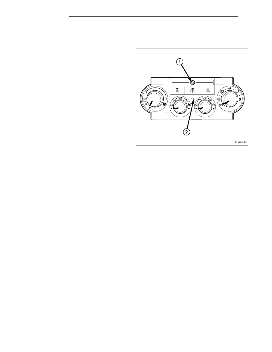
SENSOR-INFRARED
DESCRIPTION
The infrared sensor is used only on models equipped
with the automatic temperature control (ATC) heating
-A/C system. The infrared temperature sensor consists
of a infrared transducer concealed behind a clear lens
(1) located within the instrument panel mounted A/C-
heater control (2).
OPERATION
The infrared sensor detects thermal radiation emitted by the driver and front passenger seat occupants and their
surroundings and converts its data into a linear pulse width modulated (PWM) output signal which is read by the
automatic temperature control (ATC) A/C-heater control. The ATC A/C-heater control uses the infrared sensor data
as one of the inputs necessary to automatically control the interior cabin temperature level. By using thermal radi-
ation (surface temperature) measurement, rather than an air temperature measurement, the ATC heating-A/C sys-
tem is able to adjust itself to the comfort level as perceived by the occupant. This allows the ATC system to
compensate for other ambient conditions affecting comfort levels, such as solar heat gain or evaporative heat loss.
The ATC system logic responds to the infrared sensor message by calculating and adjusting the air flow tempera-
ture and air flow rate needed to properly obtain and maintain the selected comfort level temperature of the occu-
pants. The A/C-heater control continually monitors the infrared sensor circuits, and will store diagnostic trouble
codes (DTCs) for any problem it detects.
The infrared sensor is diagnosed using a scan tool (Refer to 24 - HEATING & AIR CONDITIONING - DIAGNOSIS
AND TESTING - HEATING AND A/C SYSTEMS) and to 24 - HVAC Electrical Diagnostics for more information.
The infrared sensor cannot be adjusted or repaired and, if faulty or damaged, the entire ATC A/C-heater control
must be replaced.
24 - 370
CONTROLS
LX