Content .. 2317 2318 2319 2320 ..
Chrysler 300/300 Touring/300C, Dodge Magnum. Manual - part 2319
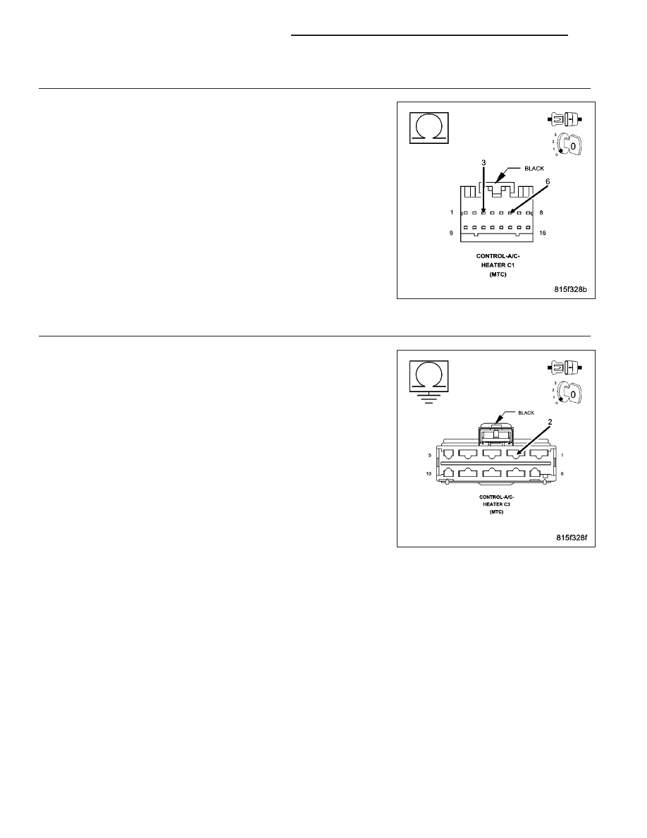
5.
CHECK THE (C850) BLOWER SWITCH POSITION SIGNAL CIRCUIT FOR A SHORT TO THE (Z909)
GROUND CIRCUIT
Disconnect the A/C Heater Control C1 harness connector.
Measure the resistance between the (C850) Blower Switch Position Sig-
nal circuit and the (Z909) Ground circuit in the A/C Heater Control C1
harness connector.
Is the resistance below 10K ohms?
Yes
>> Repair the (C850) Blower Switch Position Signal circuit for a
short to the (Z909) Ground circuit.
Perform BODY VERIFICATION TEST – VER 1. (Refer to 8
-
ELECTRICAL/ELECTRONIC
CONTROL
MODULES/
FRONT CONTROL MODULE - DIAGNOSIS AND TEST-
ING).
No
>> Go To 6
6.
CHECK THE (C850) BLOWER SWITCH POSITION SIGNAL CIRCUIT FOR A SHORT TO GROUND
Measure the resistance of the (C850) Blower Switch Position Signal cir-
cuit between ground and the A/C Heater Control C3 harness connector.
Is the resistance below 10K ohms?
Yes
>> Repair the (C850) Blower Switch Position Signal circuit for a
short to ground.
Perform BODY VERIFICATION TEST – VER 1. (Refer to 8
-
ELECTRICAL/ELECTRONIC
CONTROL
MODULES/
FRONT CONTROL MODULE - DIAGNOSIS AND TEST-
ING).
No
>> Go To 7
24 - 310
HVAC - ELECTRICAL DIAGNOSTICS
LX