Content .. 2287 2288 2289 2290 ..
Chrysler 300/300 Touring/300C, Dodge Magnum. Manual - part 2289
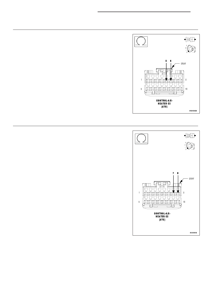
12.
CHECK THE (C255) LEFT BLEND DOOR DRIVER CIRCUIT FOR A SHORT TO THE (C55) LEFT BLEND
DOOR COMMON DRIVER CIRCUIT
Disconnect the Left Blend Door Actuator harness connector.
Measure the resistance between the (C255) Left Blend Door Driver cir-
cuit and the (C55) Left Blend Door Common Driver circuit in the A/C
Heater Control C2 harness connector.
Is the resistance below 10k ohms?
Yes
>> Repair the (C255) Left Blend Door Driver circuit for a short
to the (C55) Left Blend Door Common Driver circuit.
Perform BODY VERIFICATION TEST – VER 1. (Refer to 8
-
ELECTRICAL/ELECTRONIC
CONTROL
MODULES/
FRONT CONTROL MODULE - DIAGNOSIS AND TEST-
ING).
No
>> Replace the Left Blend Door Actuator in accordance with
the Service Information.
Perform BODY VERIFICATION TEST – VER 1. (Refer to 8
-
ELECTRICAL/ELECTRONIC
CONTROL
MODULES/
FRONT CONTROL MODULE - DIAGNOSIS AND TEST-
ING).
13.
CHECK THE RIGHT BLEND DOOR ACTUATOR CIRCUIT RESISTANCE
Measure the resistance between the (C252) Right Blend Door Driver
circuit and the (C52) Right Blend Door Common Driver circuit in the
A/C Heater Control C2 harness connector.
Is the resistance below 30.0 ohms?
Yes
>> Go To 14
No
>> Go To 15
24 - 190
HVAC - ELECTRICAL DIAGNOSTICS
LX