Chrysler 300/300 Touring/300C, Dodge Magnum. Manual - part 217


  Index      Chrysler     Chrysler 300/300 Touring/300C, Dodge Magnum - service repair manual


Search            


Content   ..  215  216  217  218   ..


Chrysler 300/300 Touring/300C, Dodge Magnum. Manual - part 217


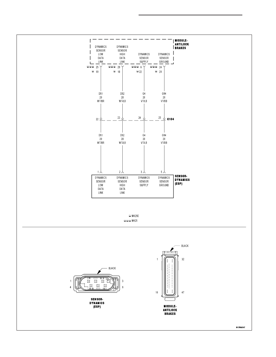
C123C-DYNAMICS SENSOR MOUNTING/INSTALLATION PERFORMANCE

For a complete wiring diagram Refer to Section 8W.

5 - 310

BRAKES - ABS ELECTRICAL DIAGNOSTICS

LX

When Monitored:
With vehicle speed above 11 km/h (7 m.p.h.), but not if the sensor signal is invalid.
Or, during skidding.
Or, when driving in reverse.

Set Condition:
If the Anti-Lock Brakes Module detects implausible Dynamics Sensor values.

Possible Causes

WIRING HARNESS, TERMINAL, CONNECTOR DAMAGE

DYNAMICS SENSOR INSTALLATION

DYNAMICS SENSOR

Diagnostic Test

1.

VERIFY DTC IS ACTIVE

NOTE: If present, diagnose and repair DTC C2114–DYNAMICS SENSOR SUPPLY VOLTAGE LOW or DTC
C2115–DYNAMICS SENSOR SUPPLY VOLTAGE HIGH before diagnosing this DTC.
Turn the ignition on.

With the scan tool, read and record ABS DTCs.

With the scan tool, read and record Environmental Data (EV Data).

With the scan tool, erase ABS DTCs.

Cycle the ignition switch.

WARNING: Ensure brake capability is available before road testing.
Test drive the vehicle by turning the vehicle left or right in a curving manner at a velocity between 10 and 20 km/hr
(6 and 12 m.p.h.).

Park the vehicle.

With the scan tool, read ABS DTCs.

Does this DTC reset?

Yes

>> Go To 2

No

>> Perform the ABS Intermittent Condition diagnostic procedure in this Section.

Perform ABS VERIFICATION TEST - VER 1. (Refer to 5 - BRAKES - STANDARD PROCEDURE).

2.

CHECK THE DYNAMICS SENSOR INSTALLATION

NOTE: Dynamics Sensor installation and mounting bolt torque is crucial for proper operation.
Turn the ignition off.

Check the Dynamics Sensor for damaged, modified, and bent mounting brackets.

Check the Dynamics Sensor mounting bolts for a loose or over tightened condition.

Were any problems found?

Yes

>> Repair as necessary.

Perform ABS VERIFICATION TEST - VER 1. (Refer to 5 - BRAKES - STANDARD PROCEDURE).

No

>> Go To 3

LX

BRAKES - ABS ELECTRICAL DIAGNOSTICS

5 - 311

3.

INSPECT RELATED WIRING HARNESS, TERMINALS, & CONNECTORS

Visually inspect the related wiring harness. Look for any pinched, chafed, pierced, and partially broken wires.

Visually inspect the related wiring harness connectors. Look for broken, bent, pushed out, and corroded terminals.

Were any problems found?

Yes

>> Repair as necessary.

Perform ABS VERIFICATION TEST - VER 1. (Refer to 5 - BRAKES - STANDARD PROCEDURE).

No

>> Replace the Dynamics Sensor in accordance with the Service Information.

Perform ABS VERIFICATION TEST - VER 1. (Refer to 5 - BRAKES - STANDARD PROCEDURE).

5 - 312

BRAKES - ABS ELECTRICAL DIAGNOSTICS

LX

C123F–STEERING ANGLE SENSOR COMPARATIVE PERFORMANCE

For a complete wiring diagram Refer to Section 8W.

LX

BRAKES - ABS ELECTRICAL DIAGNOSTICS

5 - 313


Content   ..  215  216  217  218   ..