Chrysler 300/300 Touring/300C, Dodge Magnum. Manual - part 2074


  Index      Chrysler     Chrysler 300/300 Touring/300C, Dodge Magnum - service repair manual


Search            


Content   ..  2072  2073  2074  2075   ..


Chrysler 300/300 Touring/300C, Dodge Magnum. Manual - part 2074


GRADUAL-TO-NO EMCC

This operation is to soften the change from Full or Partial EMCC to No EMCC. This is done at mid-throttle by
decreasing the L/R Solenoid duty cycle.

REMOVAL

1. Remove transmission and torque converter from vehicle. (Refer to 21 - TRANSMISSION/AUTOMATIC - 545RFE/

42RLE - REMOVAL)

2. Place a suitable drain pan under the converter housing end of the transmission.

CAUTION: Verify that transmission is secure on the lifting device or work surface, the center of gravity of
the transmission will shift when the torque converter is removed creating an unstable condition. The torque
converter is a heavy unit. Use caution when separating the torque converter from the transmission.

3. Pull the torque converter forward until the center hub clears the oil pump seal.

4. Separate the torque converter from the transmission.

INSTALLATION

NOTE: Check converter hub and drive notches for sharp edges, burrs, scratches, or nicks. Polish the hub
and notches with 320/400 grit paper or crocus cloth if necessary. The hub must be smooth to avoid dam-
aging the pump seal at installation.

1. Lubricate oil pump seal lip with transmission fluid.

2. Place torque converter in position on transmission.

CAUTION: Do not damage oil pump seal or bush-
ing while inserting torque converter into the front
of the transmission.

3. Align torque converter to oil pump seal opening.

4. Insert torque converter hub into oil pump.

5. While pushing torque converter inward, rotate con-

verter until converter is fully seated in the oil pump
gears.

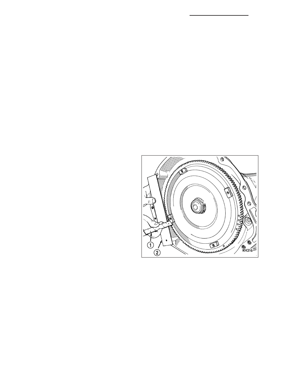
6. Check converter seating with a scale (1) and

straightedge (2). Surface of converter lugs should
be 1/2 in. to rear of straightedge when converter is
fully seated.

7. If necessary, temporarily secure converter with

C-clamp attached to the converter housing.

8. Install the transmission in the vehicle.

9. Fill the transmission with the recommended fluid.

21 - 830

AUTOMATIC TRANSMISSION 42RLE - SERVICE INFORMATION

LX

RELAY-TRANSMISSION CONTROL

DESCRIPTION

The relay is supplied fused B+ voltage, energized by the TCM, and is used to supply power to the solenoid pack
when the transmission is in normal operating mode.

OPERATION

When the relay is “off”, no power is supplied to the solenoid pack and the transmission is in “limp-in” mode. After a
controller reset, the TCM energizes the relay. Prior to this, the TCM verifies that the contacts are open by checking
for no voltage at the switched battery terminals. After this is verified, the voltage at the solenoid pack pressure
switches is checked. After the relay is energized, the TCM monitors the terminals to verify that the voltage is greater
than 3 volts.

LX

AUTOMATIC TRANSMISSION 42RLE - SERVICE INFORMATION

21 - 831

SENSOR-TRANSMISSION RANGE

DESCRIPTION

The Transmission Range Sensor (TRS) (2) is mounted
to the top of the valve body inside the transmission
and can only be serviced by removing the valve body
assembly. The electrical connector extends through
the transmission case.

The Transmission Range Sensor (TRS) has four
switch contacts that monitor shift lever position and
send the information to the PCM.

OPERATION

The Transmission Range Sensor (TRS) communicates shift lever position (SLP) to the TCM as a combination of
open and closed switches. Each shift lever position has an assigned combination of switch states (open/closed) that
the TCM receives from four sense circuits. The TCM interprets this information and determines the appropriate
transmission gear position and shift schedule.

Since there are four switches, there are 16 possible combinations of open and closed switches (codes). Seven of
these codes are related to gear position and three are recognized as “between gear” codes. This results in six
codes which should never occur. These are called “invalid” codes. An invalid code will result in a DTC, and the TCM
will then determine the shift lever position based on pressure switch data. This allows reasonably normal transmis-
sion operation with a TRS failure.

TRS SWITCH STATES

SLP

T42

T41

T3

T1

P

CL

CL

CL

OP

R

CL

OP

OP

OP

N

CL

CL

OP

CL

D

OP

OP

OP

CL

2

OP

OP

CL

OP

1

CL

OP

CL

CL

21 - 832

AUTOMATIC TRANSMISSION 42RLE - SERVICE INFORMATION

LX

REMOVAL

1. Remove valve body assembly from vehicle. (Refer

to 21 - TRANSMISSION/AUTOMATIC - 42RLE/
VALVE BODY - REMOVAL)

2. Remove the manual shaft seal (1).

3. Remove manual shaft/TRS retaining screw (1).

4. Slide TRS off of manual valve shaft.

LX

AUTOMATIC TRANSMISSION 42RLE - SERVICE INFORMATION

21 - 833


Content   ..  2072  2073  2074  2075   ..