Content .. 2001 2002 2003 2004 ..
Chrysler 300/300 Touring/300C, Dodge Magnum. Manual - part 2003
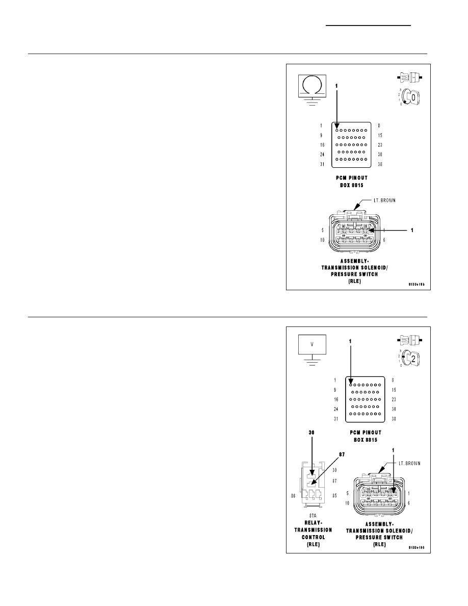
5.
(T60) OD SOLENOID CONTROL CIRCUIT SHORT TO GROUND
Turn the ignition off to the lock position.
Disconnect the PCM C4 harness connector.
Disconnect the Transmission Solenoid/Pressure Switch Assembly har-
ness connector.
Measure the resistance between ground and the (T60) OD Solenoid
Control circuit.
Is the resistance below 5.0 ohms?
Yes
>> Repair the (T60) OD Solenoid Control circuit for a short to
ground.
Perform 42RLE TRANSMISSION VERIFICATION TEST -
VER 1. (Refer to 21 - TRANSMISSION/TRANSAXLE/AU-
TOMATIC - 42RLE - STANDARD PROCEDURE)
No
>> Go To 6
6.
(T60) OD SOLENOID CONTROL CIRCUIT SHORT TO VOLTAGE
Turn the ignition off to the lock position.
Disconnect the PCM C4 harness connector.
Disconnect the Transmission Solenoid/Pressure Switch Assembly har-
ness connector.
Remove the Transmission Control Relay.
NOTE: Check connectors - Clean/repair as necessary.
Connect a jumper wire between the (Internal) Fused B+ circuit and the
(T16) Transmission Control Relay Output circuit in the Transmission
Control Relay connector.
Ignition on, engine not running.
CAUTION: Do not probe the PCM harness connectors. Probing the
PCM harness connectors will damage the PCM terminals resulting
in poor terminal to pin connection. Install Miller Special Tool #8815
to perform diagnosis.
Measure the voltage of the (T60) OD Solenoid Control circuit.
Is the voltage above 0.5 volts?
Yes
>> Repair the (T60) OD Solenoid Control circuit for a short to
voltage.
Perform 42RLE TRANSMISSION VERIFICATION TEST -
VER 1. (Refer to 21 - TRANSMISSION/TRANSAXLE/AU-
TOMATIC - 42RLE - STANDARD PROCEDURE)
No
>> Using the schematics as a guide, check the Powertrain
Control Module (PCM) terminals for corrosion, damage, or
terminal push out. Pay particular attention to all power and
ground circuits. If no problems are found, replace the PCM
21 - 546
AUTOMATIC TRANSMISSION 42RLE - ELECTRICAL DIAGNOSTICS
LX