Content .. 1987 1988 1989 1990 ..
Chrysler 300/300 Touring/300C, Dodge Magnum. Manual - part 1989
TOMATIC - 42RLE - STANDARD PROCEDURE)
14.
TRS (T42) SENSE CIRCUIT OPEN
Turn the ignition off to the lock position.
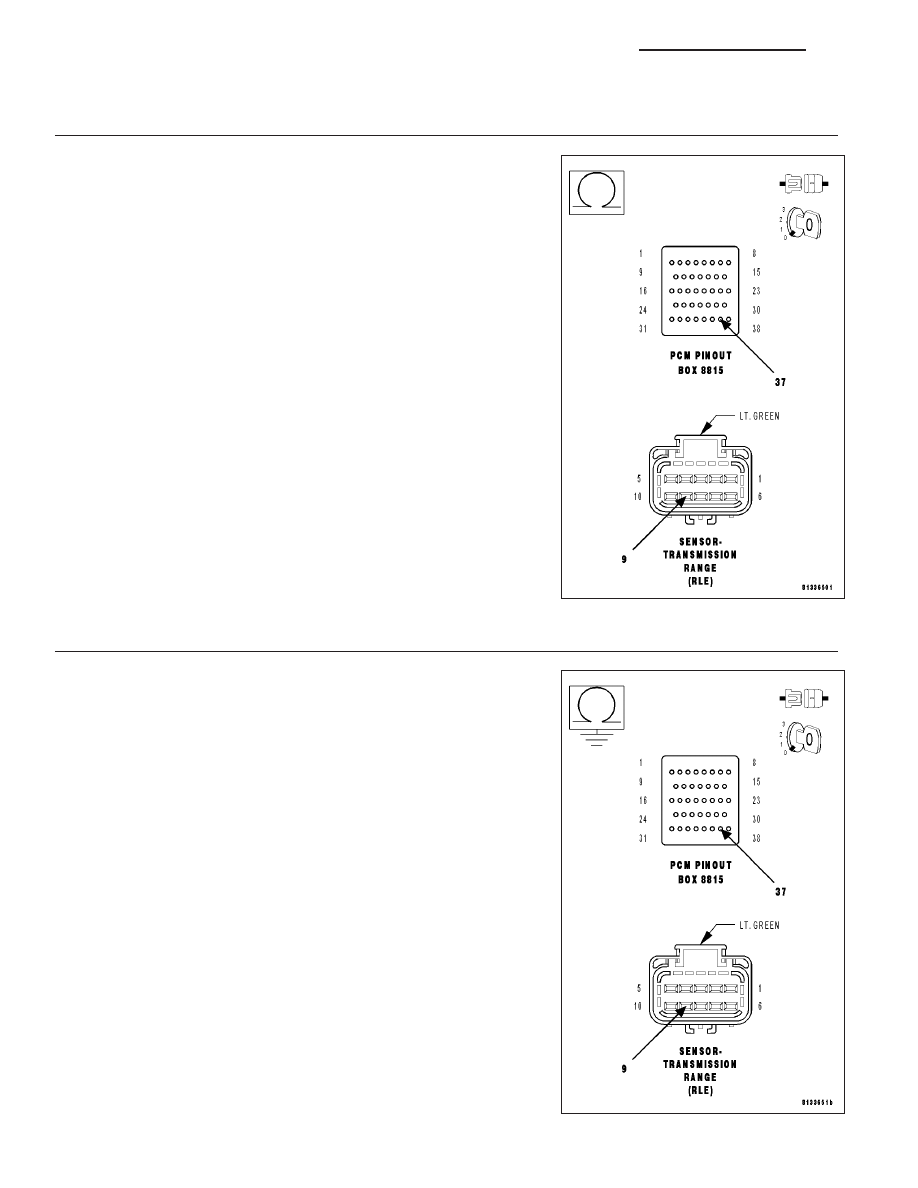
Disconnect the TRS harness connector.
Disconnect the PCM C4 harness connector.
NOTE: Check connectors - Clean/repair as necessary.
CAUTION: Do not probe the PCM harness connectors. Probing the
PCM harness connectors will damage the PCM terminals resulting
in poor terminal to pin connection. Install Miller Tool #8815 to per-
form diagnosis.
Measure the resistance of the TRS (T42) Sense circuit from the appro-
priate terminal of special tool #8815 to the TRS harness connector.
Is the resistance above 5.0 ohms?
Yes
>> Repair the TRS (T42) Sense circuit for an open.
Perform 42RLE TRANSMISSION VERIFICATION TEST -
VER 1. (Refer to 21 - TRANSMISSION/TRANSAXLE/AU-
TOMATIC - 42RLE - STANDARD PROCEDURE)
No
>> Go To 15
15.
TRS (T42) SENSE CIRCUIT SHORT TO GROUND
Turn the ignition off to the lock position.
Disconnect the TRS harness connector.
Disconnect the PCM C4 harness connector.
NOTE: Check connectors - Clean/repair as necessary.
Measure the resistance between ground and the TRS (T42) Sense cir-
cuit.
Is the resistance below 5.0 ohms?
Yes
>> Repair the TRS (T42) Sense circuit for a short to ground.
Perform 42RLE TRANSMISSION VERIFICATION TEST -
VER 1. (Refer to 21 - TRANSMISSION/TRANSAXLE/AU-
TOMATIC - 42RLE - STANDARD PROCEDURE)
No
>> Go To 16
21 - 490
AUTOMATIC TRANSMISSION 42RLE - ELECTRICAL DIAGNOSTICS
LX