Chrysler 300/300 Touring/300C, Dodge Magnum. Manual - part 187


  Index      Chrysler     Chrysler 300/300 Touring/300C, Dodge Magnum - service repair manual


Search            


Content   ..  185  186  187  188   ..


Chrysler 300/300 Touring/300C, Dodge Magnum. Manual - part 187


6.

(G14) ADJUSTABLE PEDALS SENSOR SIGNAL CIRCUIT SHORT TO GROUND

Connect a jumper wire between the (G14) Adjustable Pedals Sensor
Signal circuit and ground at the Adjustable Pedal Sensor harness con-
nector.

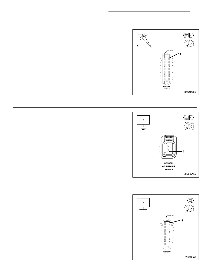
Using a 12-volt test light connected to 12-volts, probe the (G14) Adjust-
able Pedals Sensor Signal circuit at the Memory Seat Module C1 har-
ness connector.

Does the test light illuminate brightly?

Yes

>> Go To 7

No

>> Repair the (G14) Adjustable Pedals Sensor Signal circuit for

an open.

Perform APS VERIFICATION TEST - VER 1. (Refer to 5 -
BRAKES - STANDARD PROCEDURE).

7.

(G13) ADJUSTABLE PEDALS SENSOR SIGNAL CIRCUIT FOR AN OPEN

Measure the voltage between the (G13) Adjustable Pedals Sensor Sup-
ply circuit and ground at the Adjustable Pedal Sensor harness connec-
tor.

Is the voltage between 4.0 and 5.0 volts?

Yes

>> Go To 8

No

>> Replace and reprogram the Seat Memory Module in accor-

dance with the Service Information.

Perform APS VERIFICATION TEST - VER 1. (Refer to 5 -
BRAKES - STANDARD PROCEDURE).

8.

(G14) ADJUSTABLE PEDALS SENSOR SIGNAL CIRCUIT VOLTAGE

Reconnect Adjustable Pedal Sensor harness connector.

Turn ignition on.

Measure the voltage of the (G14) Adjustable Pedals Sensor Signal cir-
cuit in the Seat Memory Module C1 harness connector.

Is the voltage above 0.5 volts?

Yes

>> Replace the Seat Memory Module in accordance with the

Service Information.

Perform APS VERIFICATION TEST - VER 1. (Refer to 5 -
BRAKES - STANDARD PROCEDURE).

No

>> Replace the Adjustable Pedals Sensor in accordance with

the Service Information.

Perform APS VERIFICATION TEST - VER 1. (Refer to 5 -
BRAKES - STANDARD PROCEDURE).

5 - 190

BRAKES - ABS ELECTRICAL DIAGNOSTICS

LX

B1D57–ADJUSTABLE PEDAL SENSOR CIRCUIT HIGH

For a complete wiring diagram Refer to Section 8W.

LX

BRAKES - ABS ELECTRICAL DIAGNOSTICS

5 - 191

When Monitored:
The Adjustable Pedal Motor is in active operation.

Set Condition:
The Memory Seat Module detects a high signal circuit voltage that is not within voltage specification from the
Adjustable Pedal Sensor.

Possible Causes

WIRING HARNESS CONNECTOR/TERMINALS

(G13) ADJUSTABLE PEDALS SENSOR SUPPLY CIRCUIT SHORT TO VOLTAGE

(G14) ADJUSTABLE PEDALS SENSOR SIGNAL CIRCUIT SHORT TO VOLTAGE

ADJUSTABLE PEDALS SENSOR

MEMORY SEAT MODULE

Diagnostic Test

1.

DTC IS ACTIVE

Turn the ignition on.

With the scan tool, select view DTCs. Record all DTC information.

With the scan tool, clear stored DTCs.

Cycle the ignition switch off then on.

Move the Adjustable Pedals Switch forward and rearward several times.

With the scan tool, select view DTCs.

Is the status active for this DTC?

Yes

>> Go To 2

No

>> Refer to the Adjustable Pedal System intermittent condition test. (Refer to 5 - BRAKES - DIAGNOSIS

AND TESTING)

2.

WIRING HARNESS CONNECTOR/TERMINALS

Turn the ignition off.

Disconnect the Memory Seat Module harness connector.

Disconnect the Adjustable Pedals Sensor harness connector.

Inspect the wiring harness, connectors and terminals.

Were any problems found?

Yes

>> Repair as necessary.

Perform APS VERIFICATION TEST. (Refer to 5 - BRAKES - STANDARD PROCEDURE).

No

>> Go To 3

5 - 192

BRAKES - ABS ELECTRICAL DIAGNOSTICS

LX

3.

(G13) ADJUSTABLE PEDALS SENSOR SUPPLY CIRCUIT SHORT TO VOLTAGE

Turn the ignition on.

Measure the voltage of the (G13) Adjustable Pedals Sensor Supply cir-
cuit and ground at the Memory Seat Module C1 harness connector.

Is there any voltage present?

Yes

>> Repair the (G13) Adjustable Pedals Sensor Supply circuit

for a short to voltage.

Perform APS VERIFICATION TEST. (Refer to 5 - BRAKES
- STANDARD PROCEDURE).

No

>> Go To 4

4.

(G14) ADJUSTABLE PEDALS SENSOR SIGNAL CIRCUIT SHORT TO VOLTAGE

Measure the voltage of the (G14) Adjustable Pedals Sensor Signal cir-
cuit and ground at the Memory Seat Module C1 harness connector.

Is there any voltage present?

Yes

>> Repair the (G14) Adjustable Pedals Sensor Signal circuit

for a short to voltage.

Perform APS VERIFICATION TEST. (Refer to 5 - BRAKES
- STANDARD PROCEDURE).

No

>> Go To 5

5.

(G14) ADJUSTABLE PEDALS SENSOR SIGNAL CIRCUIT VOLTAGE

Turn the ignition off.

Reconnect all connectors.

Measure the voltage of the (G14) Adjustable Pedals Sensor Signal cir-
cuit at the Memory Seat Module C1 harness connector.

Is the voltage below 4.0 volts?

Yes

>> Replace and reprogram the Memory Seat Module in accor-

dance with the Service Information.

Perform APS VERIFICATION TEST. (Refer to 5 - BRAKES
- STANDARD PROCEDURE).

No

>> Replace the Adjustable Pedals Sensor in accordance with

the Service Information.

Perform APS VERIFICATION TEST. (Refer to 5 - BRAKES
- STANDARD PROCEDURE).

LX

BRAKES - ABS ELECTRICAL DIAGNOSTICS

5 - 193


Content   ..  185  186  187  188   ..