Content .. 1805 1806 1807 1808 ..
Chrysler 300/300 Touring/300C, Dodge Magnum. Manual - part 1807
3.
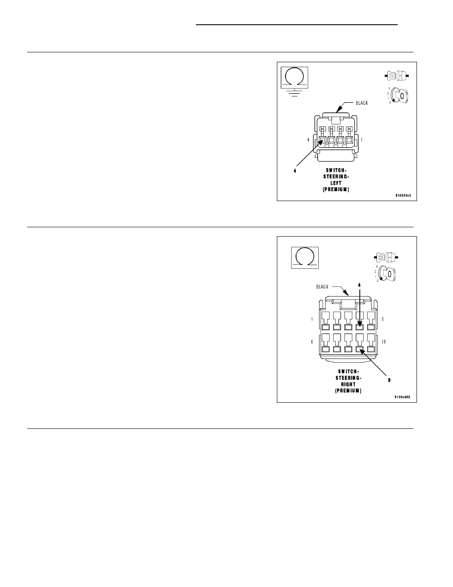
(G206) EVIC MUX SIGNAL 1 CIRCUIT SHORT TO GROUND
NOTE: Before proceeding, thoroughly inspect the wiring harness
and connectors between the Left Steering Switch and the Right
Steering Switch for a short to ground or any other circuit.
Measure the resistance between the (G206) EVIC Mux Signal 1 circuit
and ground.
Is the resistance below 5.0 ohms?
Yes
>> Repair the (G206) EVIC Mux Signal 1 circuit for a short to
ground.
No
>> Go to 4
4.
LEFT STEERING SWITCH
Reconnect the Left Steering Switch harness connector.
Measure the resistance between the (G206) EVIC Mux Signal 1 circuit
and the (G907) EVIC/NAV Mux Return circuit at the Right Steering
Switch harness connector.
Is the resistance approximately .5 ohms (+/- 1 ohm)?
Yes
>> Replace the Left Steering Switch in accordance with the
Service Information.
No
>> Go to 5
5.
RIGHT STEERING SWITCH
Replace the Right Steering Switch in accordance with the Service Information.
Reconnect the C206 (LIN Bus) connector.
Turn the ignition on.
Press and release the Side Switch several times.
With the scan tool, Clear Stored DTCs in the Steering Control Module.
With the scan tool, select Data Display and view the Side switch data.
While monitoring the Side switch data, press and release the Side Switch several times.
Does the Side switch data change from Set to Not Set as the switch is pressed and released?
Yes
>> Test complete.
No
>> Go to 6
19 - 46
COLUMN ELECTRICAL DIAGNOSIS
LX