Content .. 1695 1696 1697 1698 ..
Chrysler 300/300 Touring/300C, Dodge Magnum. Manual - part 1697
REMOVAL
WARNING: The normal operating temperature of
the exhaust system is very high. therefore, never
work around or attempt to service any part of the
exhaust system until it is cooled. special care
should be taken when working near the catalytic
converter. The temperature of the converter rises
to a high level after a short period of engine oper-
ation time.
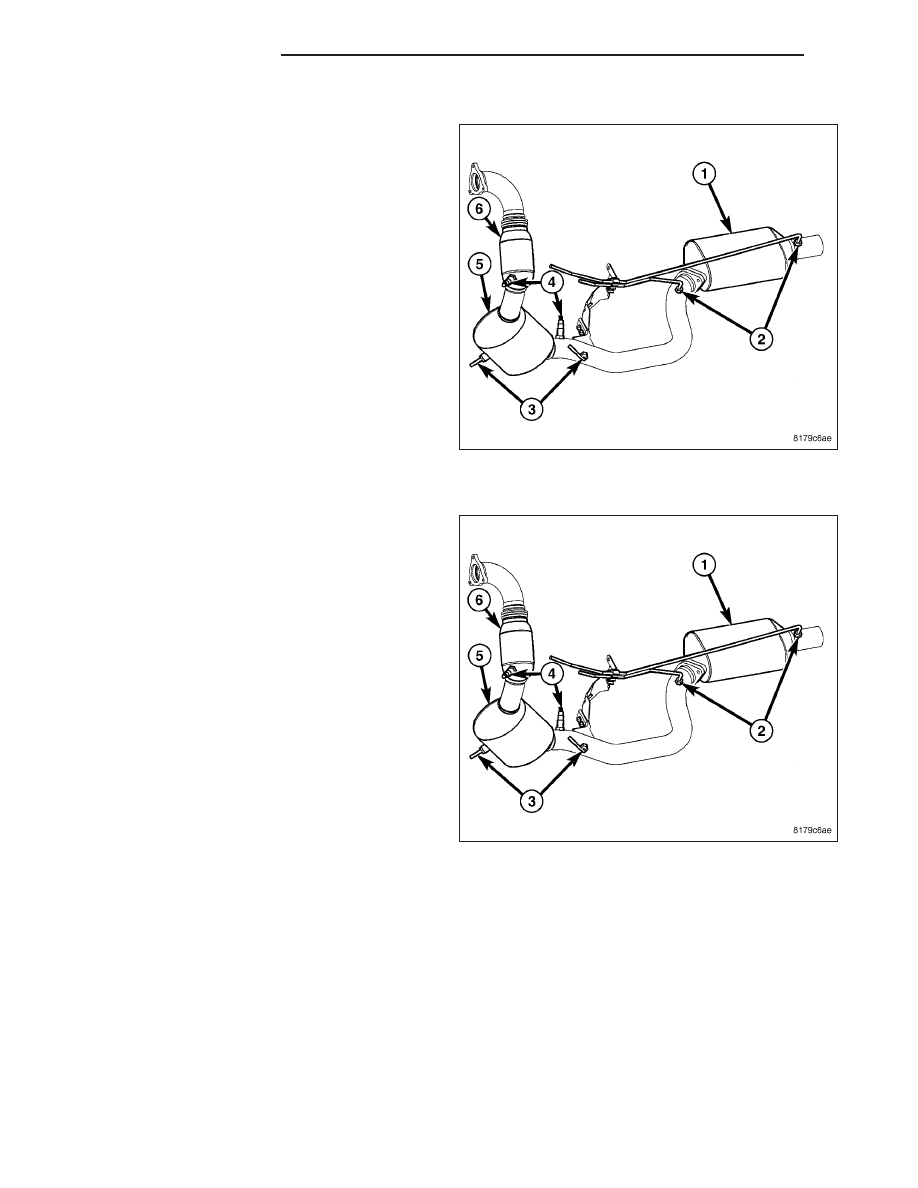
1. Disconnect negative battery cable.
2. Disconnect differential pressure ports (2).
3. Remove exhaust from the diesel particulate filter
(1).
4. Remove the catalyst to diesel particulate filter fas-
teners.
5. Remove the diesel particulate filter assembly.
INSTALLATION
WARNING: The normal operating temperature of
the exhaust system is very high. therefore, never
work around or attempt to service any part of the
exhaust system until it is cooled. special care
should be taken when working near the catalytic
converter. The temperature of the converter rises
to a high level after a short period of engine oper-
ation time.
1. Install the diesel particulate filter assembly (1).
2. Install the catalyst to diesel particulate filter fasten-
ers.
3. Reconnect the exhaust to the diesel particulate fil-
ter (1).
4. Connect differential pressure ports (2).
5. Connect negative battery cable.
11 - 22
EXHAUST SYSTEM
LX