Chrysler 300/300 Touring/300C, Dodge Magnum. Manual - part 1620


  Index      Chrysler     Chrysler 300/300 Touring/300C, Dodge Magnum - service repair manual


Search            


Content   ..  1618  1619  1620  1621   ..


Chrysler 300/300 Touring/300C, Dodge Magnum. Manual - part 1620


5. The valve seat must maintain an angle of 44.5 –

45.0 degrees angle.

6. The valve face must maintain a face angle of 45.5

– 46.0 degrees angle for the Intake, and 45.0 –
45.5 degrees angle for the exhaust .

REMOVAL

1. Remove the cylinder head (Refer to 9 - ENGINE/CYLINDER HEAD - REMOVAL).

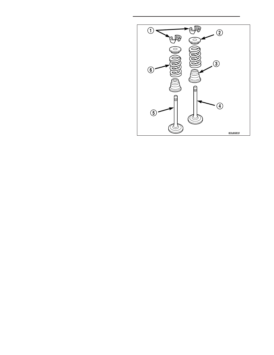
2. Compress valve springs using Valve Spring Compressor Tool special tool # C-3422and adapter 8464.

3. Remove valve retaining locks, valve spring retainers, valve stem seals and valve springs.

4. Before removing valves, remove any burrs from valve stem lock grooves to prevent damage to the valve guides.

Identify valves to ensure installation in original location.

INSTALLATION

1. Clean valves thoroughly. Discard burned, warped and cracked valves.

2. Remove carbon and varnish deposits from inside of valve guides with a reliable guide cleaner.

3. Measure valve stems for wear. If wear exceeds 0.051 mm (0.002 inch), replace the valve.

4. Coat valve stems with lubrication oil and insert them in cylinder head.

5. If valves or seats are reground, check valve stem height. If valve is too long, replace cylinder head.

6. Install new seals on all valve guides. Install valve springs and valve retainers.

7. Compress valve springs with Valve Spring Compressor Tool special tool # C- 3422and adapter 8464, install locks

and release tool. If valves and/or seats are ground, measure the installed height of springs. Make sure the mea-
surement is taken from bottom of spring seat in cylinder head to the bottom surface of spring retainer.

8. Install cylinder head (Refer to 9 - ENGINE/CYLINDER HEAD - INSTALLATION).

9 - 2504

ENGINE - 6.1L SERVICE INFORMATION

LX

ROCKER ARM

REMOVAL

1. Remove

cylinder

head

cover.

(Refer

to

9

-

ENGINE/CYLINDER

HEAD/CYLINDER

HEAD

COVER(S) - REMOVAL).

2. Install pushrod retaining plate (1)special tool 9070.

LX

ENGINE - 6.1L SERVICE INFORMATION

9 - 2505

3. Loosen the rocker shafts using the sequence pro-

vided.

CAUTION: The rocker shaft assemblies are not
interchangeable between intake and exhaust. The
intake rocker arms are marked with an “I”.

4. Remove the rocker shafts. Note location for reas-

sembly.

CAUTION: The longer push rods are for the
exhaust side, and the shorter push rods are for
intake side.

5. Remove the pushrods. Note pushrod location for

reassembly.

CAUTION: Do not remove the retainers from the rocker shaft. The assembly tangs (1) at the bottom of the
retainers (2) can be damaged, causing the assembly tangs to break off, and get into the engine.

9 - 2506

ENGINE - 6.1L SERVICE INFORMATION

LX

INSTALLATION

CAUTION: The longer push rods are for the
exhaust side, and the shorter push rods are for
intake side.

1. Install the push rods in the same order as

removed.

2. Install the pushrod retaining plate (1) special tool

9070.

CAUTION: Ensure that retainers (2) and rocker arms (4) are not overlapped when torquing bolts.

CAUTION: Verify that pushrod is installed into rocker arm (4) and tappet correctly while installing rocker
shaft assembly. Recheck after rocker shaft has been torqued to specification.

LX

ENGINE - 6.1L SERVICE INFORMATION

9 - 2507


Content   ..  1618  1619  1620  1621   ..