Chrysler 300/300 Touring/300C, Dodge Magnum. Manual - part 142
FRONT BRAKES
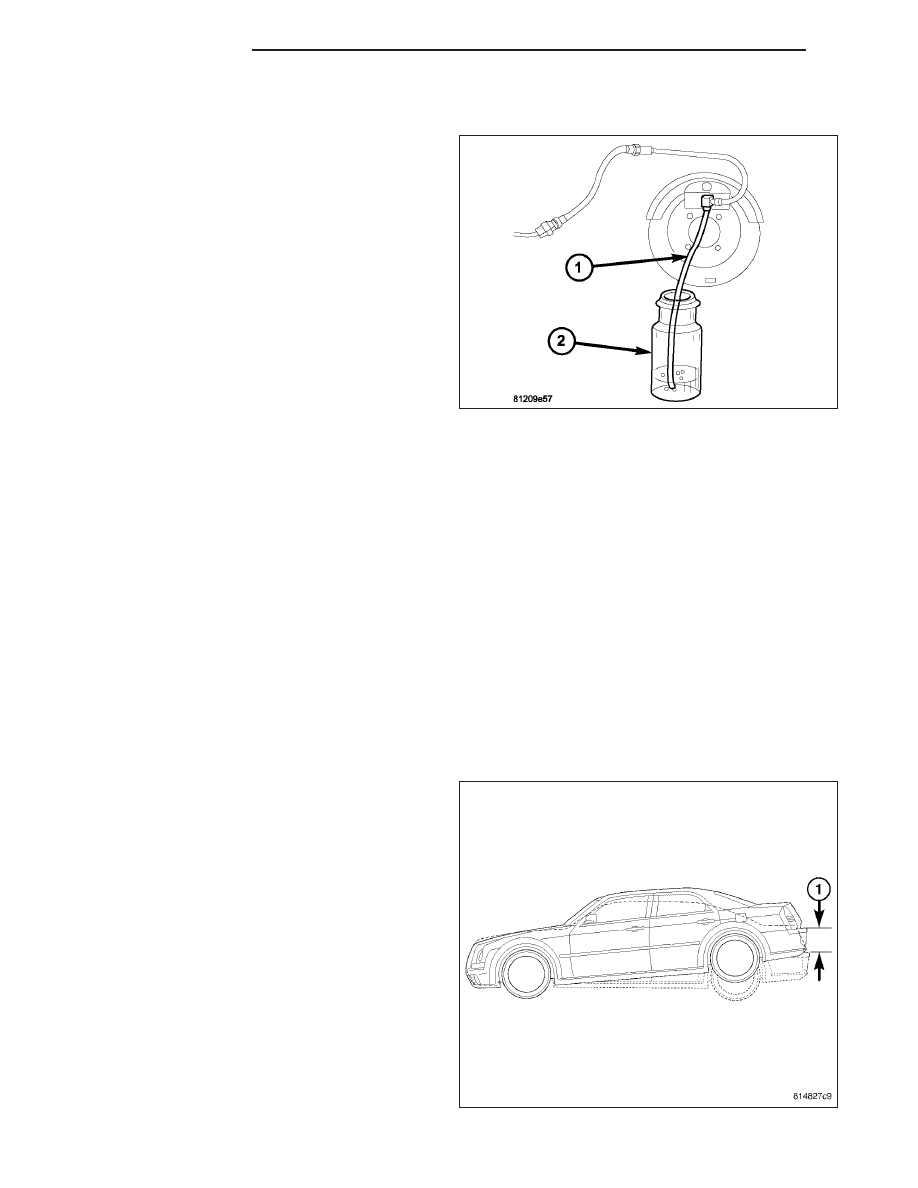
1. If installed, remove rubber dust cap from bleeder
screw on each front brake caliper.
2. Starting at the first wheel circuit that needs to be
bled (See list in above note), attach a clear hose
(1) to the bleeder screw at that wheels brake cali-
per and feed the other end of hose into a clear jar
(2) containing enough fresh brake fluid to sub-
merge the end of the hose.
CAUTION: Open the bleeder screw at least one full
turn when instructed. Some air may be trapped in
the brake lines or valves far upstream, as far as
ten feet or more from the bleeder screw. If the
bleeder screw is not opened sufficiently, fluid flow
is restricted causing a slow, weak fluid discharge.
This will NOT get all the air out. Therefore, it is
essential to open the bleeder screw at least one
full turn to allow a fast, large volume discharge of brake fluid.
3. Open bleeder screw at least one full turn or more to obtain an adequate flow of brake fluid.
4. After 4 to 8 ounces of brake fluid has been bled through the brake hydraulic circuit, and an air-free flow (no
bubbles) is maintained in the clear plastic hose (1) and jar (2), close the bleeder screw.
5. Install bleeder screw dust cap.
6. Bleed opposite front brake wheel circuit as necessary in the same manner until all air is removed from the brake
hydraulic system.
5. If equipped with antilock brakes, the hydraulic control unit may need to be bled, then rebleed base brakes. (Refer
to 5 - BRAKES - STANDARD PROCEDURE)
6. Once all brakes are bled, check brake pedal travel. If pedal travel is excessive or has not improved, some air
may still be trapped in the hydraulic system. Rebleed the brake system as necessary.
7. Test drive vehicle to ensure brakes are operating properly and pedal feel is correct.
MANUAL BLEEDING METHOD
NOTE: To bleed the base brake system manually, an assistants help is required.
NOTE: To ensure all air is bled from the ICU or
junction block in a timely manner, it is recom-
mended to raise the rear of the vehicle approxi-
mately 5° higher than the front or approximately
10–12 inches as measured at the rear bumper (1).
1. Raise and support vehicle placing rear of vehicle
approximately 5° higher than the front or if mea-
sured at the rear bumper (1), approximately 10–12
inches above level. It will be necessary to add
extra support stands under vehicle to support this
angle.
5 - 10
BRAKES - BASE
LX