Chrysler 300/300 Touring/300C, Dodge Magnum. Manual - part 1415


  Index      Chrysler     Chrysler 300/300 Touring/300C, Dodge Magnum - service repair manual


Search            


Content   ..  1413  1414  1415  1416   ..


Chrysler 300/300 Touring/300C, Dodge Magnum. Manual - part 1415


2.

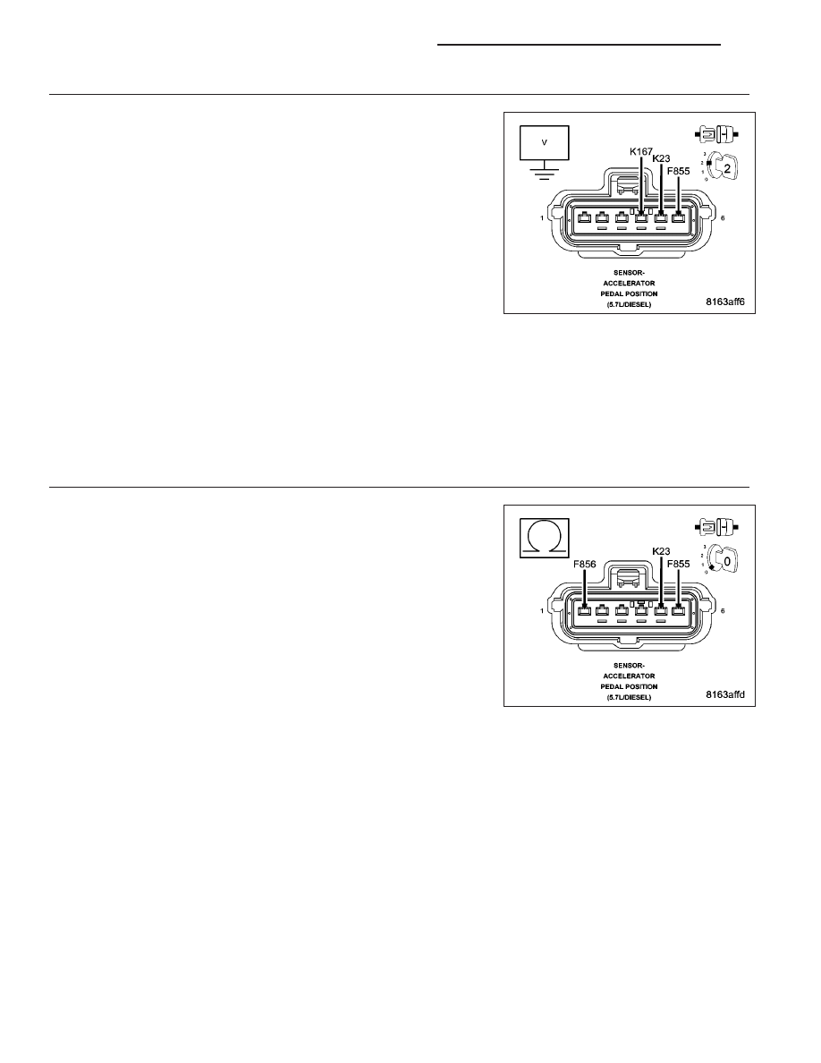
ACCELERATOR PEDAL POSITION SENSOR CIRCUIT SHORTED TO VOLTAGE

Turn the ignition off.

Disconnect the Accelerator Pedal Position Sensor connector.

Disconnect the Engine Control Module (ECM) connector.

Remove the ASD Relay from the IPM.

Connect a jumper wire between cavity 30 and cavity 87 of the ASD
Relay Connector.

Turn the ignition on.

Measure the voltage of the (F855) Accelerator Pedal Position Sensor
No. 1 5 Volt Supply circuit in the Accelerator Pedal Position Sensor con-
nector.

Measure the voltage of the (K23) Accelerator Pedal Position Sensor No.
1 Signal circuit in the Accelerator Pedal Position Sensor connector.

Measure the voltage of the (K167) Accelerator Pedal Position Sensor
No. 1 Sensor Ground circuit in the Accelerator Pedal Position Sensor connector.

Is there voltage present on any of the circuits?

Yes

>> Repair the appropriate circuit that has voltage present.

Perform the ECM Verification Test Ver. 1. (Refer to 9 - ENGINE - DIAGNOSIS AND TESTING)

No

>> Go to 3

3.

(K23) ACCELERATOR PEDAL POSITION SENSOR NO. 1 SIGNAL CIRCUIT SHORTED TO THE 5 VOLT
SUPPLY CIRCUIT

Turn the ignition off.

Disconnect the Engine Control Module (ECM) connector.

Measure the resistance between the (K23) Accelerator Pedal Position
Sensor No. 1 Signal circuit and the (F855) Accelerator Pedal Position
Sensor No. 1 5 Volt Supply circuit in the Accelerator Pedal Position
Sensor connector.

Measure the resistance between the (K23) Accelerator Pedal Position
Sensor No. 1 Signal circuit and the (F856) Accelerator Pedal Position
Sensor No. 2 5 Volt Supply circuit in the Accelerator Pedal Position
Sensor connector.

Is the resistance above 10.0 ohms for both of the circuits?

Yes

>> Go to 4

No

>> Repair the shorted (K23) Accelerator Pedal Position Sensor

No. 1 Signal circuit.

Perform the ECM Verification Test Ver. 1. (Refer to 9 - ENGINE - DIAGNOSIS AND TESTING)

9 - 1684

ENGINE ELECTRICAL DIAGNOSTICS - DIESEL

LX

4.

ACCELERATOR PEDAL POSITION SENSOR CIRCUIT OPEN OR HIGH RESISTANCE

Turn the ignition off.

Disconnect the Engine Control Module (ECM) connector.

Measure the resistance of the (F855) Accelerator Pedal Position Sensor
No. 1 5 Volt Supply circuit between the Accelerator Pedal Position Sen-
sor connector and the Engine Control Module (ECM) connector.

Measure the resistance of the (K23) Accelerator Pedal Position Sensor
No. 1 Signal circuit between the Accelerator Pedal Position Sensor con-
nector and the Engine Control Module (ECM) connector.

Measure the resistance of the (K167) Accelerator Pedal Position Sensor
No. 1 Sensor Ground circuit between the Accelerator Pedal Position
Sensor connector and the Engine Control Module (ECM) connector.

Is the resistance below 10.0 ohms for each of the circuits?

Yes

>> Go to 5

No

>> Repair the appropriate circuit for an open circuit or high

resistance.

Perform the ECM Verification Test Ver. 1. (Refer to 9 -
ENGINE - DIAGNOSIS AND TESTING)

5.

ACCELERATOR PEDAL POSITION SENSOR

Turn the ignition off.

Remove the jumper wire and install the ASD Relay.

Connect the Engine Control Module (ECM) connector.

Connect a jumper wire between the (K167) Accelerator Pedal Position
Sensor No. 1 Sensor Ground circuit and the (K23) Accelerator Pedal
Position Sensor No. 1 Signal circuit in the Accelerator Pedal Position
Sensor connector.

Turn the ignition on.

With the scan tool, Clear DTCs.

Fully depress and release the Accelerator Pedal several times.

With the scan tool, select View DTCs.

NOTE: The scan tool should display an Accelerator Pedal Position
Sensor No. 1 low voltage or short to ground DTC with the jumper
wire in place.

Does the scan tool display the DTC as described above?

Yes

>> Replace the Accelerator Pedal Position Sensor in accordance with the Service Information.

Perform the ECM Verification Test Ver. 1. (Refer to 9 - ENGINE - DIAGNOSIS AND TESTING)

No

>> Go to 6

LX

ENGINE ELECTRICAL DIAGNOSTICS - DIESEL

9 - 1685

6.

ENGINE CONTROL MODULE (ECM)

Using the wiring diagram/schematic as a guide, inspect the wiring and connectors between the Accelerator Pedal
Position Sensor and the Engine Control Module (ECM).

Look for any chafed, pierced, pinched, or partially broken wires.

Look for broken, bent, pushed out or corroded terminals.

Monitor the scan tool data relative to this circuit and wiggle test the wiring and connectors.

Look for the data to change or for the DTC to reset during the wiggle test.

Refer to any Technical Service Bulletins that may apply.

Were any problems found?

Yes

>> Repair as necessary.

Perform the ECM Verification Test Ver. 1. (Refer to 9 - ENGINE - DIAGNOSIS AND TESTING)

No

>> Replace the Engine Control Module (ECM) in accordance with the Service Information.

Perform the ECM Verification Test Ver. 1. (Refer to 9 - ENGINE - DIAGNOSIS AND TESTING)

9 - 1686

ENGINE ELECTRICAL DIAGNOSTICS - DIESEL

LX

P2127-ACCELERATOR PEDAL POSITION SENSOR 2 CIRCUIT LOW

For a complete wiring diagram Refer to Section 8W

LX

ENGINE ELECTRICAL DIAGNOSTICS - DIESEL

9 - 1687


Content   ..  1413  1414  1415  1416   ..