Chrysler 300/300 Touring/300C, Dodge Magnum. Manual - part 1375


  Index      Chrysler     Chrysler 300/300 Touring/300C, Dodge Magnum - service repair manual


Search            


Content   ..  1373  1374  1375  1376   ..


Chrysler 300/300 Touring/300C, Dodge Magnum. Manual - part 1375


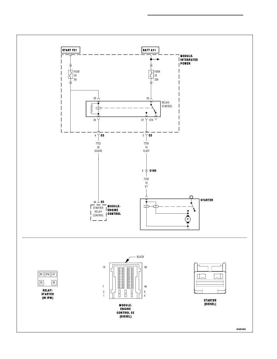
P0615-STARTER CONTROL CIRCUIT/OPEN

For a complete wiring diagram Refer to Section 8W

9 - 1524

ENGINE ELECTRICAL DIAGNOSTICS - DIESEL

LX

When Monitored:
With the ignition on and the Starter Relay command off.

Set Condition:
The ECM does not detect voltage on the (T752) Engine Starter Motor Relay Control circuit for 1.0 second.

Possible Causes

INTERMITTENT DTC

(T752) ENGINE STARTER MOTOR RELAY CONTROL CIRCUIT SHORTED TO GROUND

(T752) ENGINE STARTER MOTOR RELAY CONTROL CIRCUIT OPEN OR HIGH RESISTANCE

(T751) FUSED IGNITION SWITCH OUTPUT (START) CIRCUIT OPEN OR HIGH RESISTANCE

STARTER RELAY

ENGINE CONTROL MODULE (ECM)

Always perform the Pre-Diagnostic Troubleshooting procedure before proceeding. (Refer to 9 - ENGINE -
DIAGNOSIS AND TESTING)

Diagnostic Test

1.

DTC IS ACTIVE

Ignition on, engine not running.

With the scan tool, Clear DTCs in the Engine Control Module (ECM).

Crank the engine for five seconds.

With the scan tool, select View DTCs.

Is the status Active for this DTC?

Yes

>> Go To 2

No

>> Refer to the *CHECKING FOR AN INTERMITTENT DTC Diagnostic Procedure. (Refer to 9 - ENGINE -

DIAGNOSIS AND TESTING)

2.

(T752) ENGINE STARTER MOTOR RELAY CONTROL CIRCUIT SHORTED TO GROUND

Turn the ignition off.

Remove the Starter Relay.

Disconnect the Engine Control Module (ECM) connector.

Measure the resistance between ground and the (T752) Engine Starter
Motor Relay Control circuit in the Starter Relay connector.

Is the resistance above 10.0 ohms?

Yes

>> Go to 3

No

>> Repair the (T752) Engine Starter Motor Relay Control circuit

for a short to ground.

Perform the ECM Verification Test Ver. 1. (Refer to 9 -
ENGINE - DIAGNOSIS AND TESTING)

LX

ENGINE ELECTRICAL DIAGNOSTICS - DIESEL

9 - 1525

3.

(T752) ENGINE STARTER MOTOR RELAY CONTROL CIRCUIT OPEN OR HIGH RESISTANCE

Measure the resistance of the (T752) Engine Starter Motor Relay Con-
trol circuit between the Starter Relay connector and the Engine Control
Module (ECM) connector.

Is the resistance below 10.0 ohms?

Yes

>> Go to 4

No

>> Repair the (T752) Engine Starter Motor Relay Control circuit

for an open circuit or high resistance.

Perform the ECM Verification Test Ver. 1. (Refer to 9 -
ENGINE - DIAGNOSIS AND TESTING)

4.

(T751) FUSED IGNITION SWITCH OUTPUT (START) CIRCUIT OPEN OR HIGH RESISTANCE

Turn the Ignition Switch to the Start position.

Using a 12-volt test light connected to ground, check the Fused Ignition
Switch Output (START) circuit at the Starter Relay connector in the IPM.

Using a 12-volt test light connected to ground, check the Ignition Switch
Start Output circuit at the ECM harness connector.

NOTE: The test light should be illuminated and bright. Compare
the brightness to that of a direct connection to the battery.

Is the test light illuminated and bright for each circuit?

Yes

>> Go to 5

No

>> Repair the (T751) Fused Ignition Switch Output (START)

circuit for an open circuit or high resistance.

Perform the ECM Verification Test Ver. 1. (Refer to 9 -
ENGINE - DIAGNOSIS AND TESTING)

5.

STARTER RELAY

Turn the ignition off.

Connect the Engine Control Module (ECM) connector.

Install a known good relay in place of the vehicle’s Starter Relay.

Turn the ignition on.

With the scan tool, Clear DTCs.

With the scan tool, actuate the Starter Relay.

Monitor the scan tool for at least two minutes.

With the scan tool, select View DTCs.

Is the status Active for this DTC?

Yes

>> Go to 6

No

>> Replace the Starter Relay in accordance with the Service Information.

Perform the ECM Verification Test Ver. 1. (Refer to 9 - ENGINE - DIAGNOSIS AND TESTING)

9 - 1526

ENGINE ELECTRICAL DIAGNOSTICS - DIESEL

LX

6.

ENGINE CONTROL MODULE (ECM)

Using the wiring diagram/schematic as a guide, inspect the wiring and connectors between the Starter Relay and
the Engine Control Module (ECM).

Look for any chafed, pierced, pinched, or partially broken wires.

Look for broken, bent, pushed out or corroded terminals.

Refer to any Technical Service Bulletins that may apply.

Were any problems found?

Yes

>> Repair as necessary.

Perform the ECM Verification Test Ver. 1. (Refer to 9 - ENGINE - DIAGNOSIS AND TESTING)

No

>> Replace the Engine Control Module (ECM) in accordance with the Service Information.

Perform the ECM Verification Test Ver. 1. (Refer to 9 - ENGINE - DIAGNOSIS AND TESTING)

LX

ENGINE ELECTRICAL DIAGNOSTICS - DIESEL

9 - 1527


Content   ..  1373  1374  1375  1376   ..