Chrysler 300/300 Touring/300C, Dodge Magnum. Manual - part 1166


  Index      Chrysler     Chrysler 300/300 Touring/300C, Dodge Magnum - service repair manual


Search            


Content   ..  1164  1165  1166  1167   ..


Chrysler 300/300 Touring/300C, Dodge Magnum. Manual - part 1166


P1618-SENSOR REFERENCE VOLTAGE 1 CIRCUIT ERRATIC

For a complete wiring diagram Refer to Section 8W.

When Monitored:
Ignition on.

Set Condition:
When the PCM recognizes the Primary 5-volt Supply circuit voltage is varying too much to quickly. One Trip
Fault. ETC light is flashing.

Possible Causes

(F855) PRIMARY 5-VOLT SUPPLY SHORTED TO GROUND

(F855) PRIMARY 5-VOLT SUPPLY SHORTED TO BATTERY VOLTAGE

(F855) PRIMARY 5-VOLT SUPPLY CIRCUIT OPEN

5-VOLT SENSOR

PCM

Always perform the Pre-Diagnostic Troubleshooting procedure before proceeding. (Refer to 9 - ENGINE -
DIAGNOSIS AND TESTING).

Diagnostic Test

1.

ACTIVE DTC

Ignition on, engine not running.

With a scan tool, read DTCs.

Is the DTC active at this time?

Yes

>> Go To 2

No

>> Refer to the INTERMITTENT CONDITION Diagnostic Procedure.

Perform the POWERTRAIN VERIFICATION TEST. (Refer to 9 - ENGINE - STANDARD PROCEDURE)

2.

(F855) PRIMARY 5-VOLT SUPPLY CIRCUIT SHORTED TO GROUND

Turn the ignition off.

Disconnect the PCM harness connectors.

Disconnect all the Sensors that share the (F855) Primary 5-volt Supply
circuit.

NOTE: This code can be caused by the improper installation of
after market accessories that may be causing excessive noise on
the (F855) 5-volt Supply circuit.
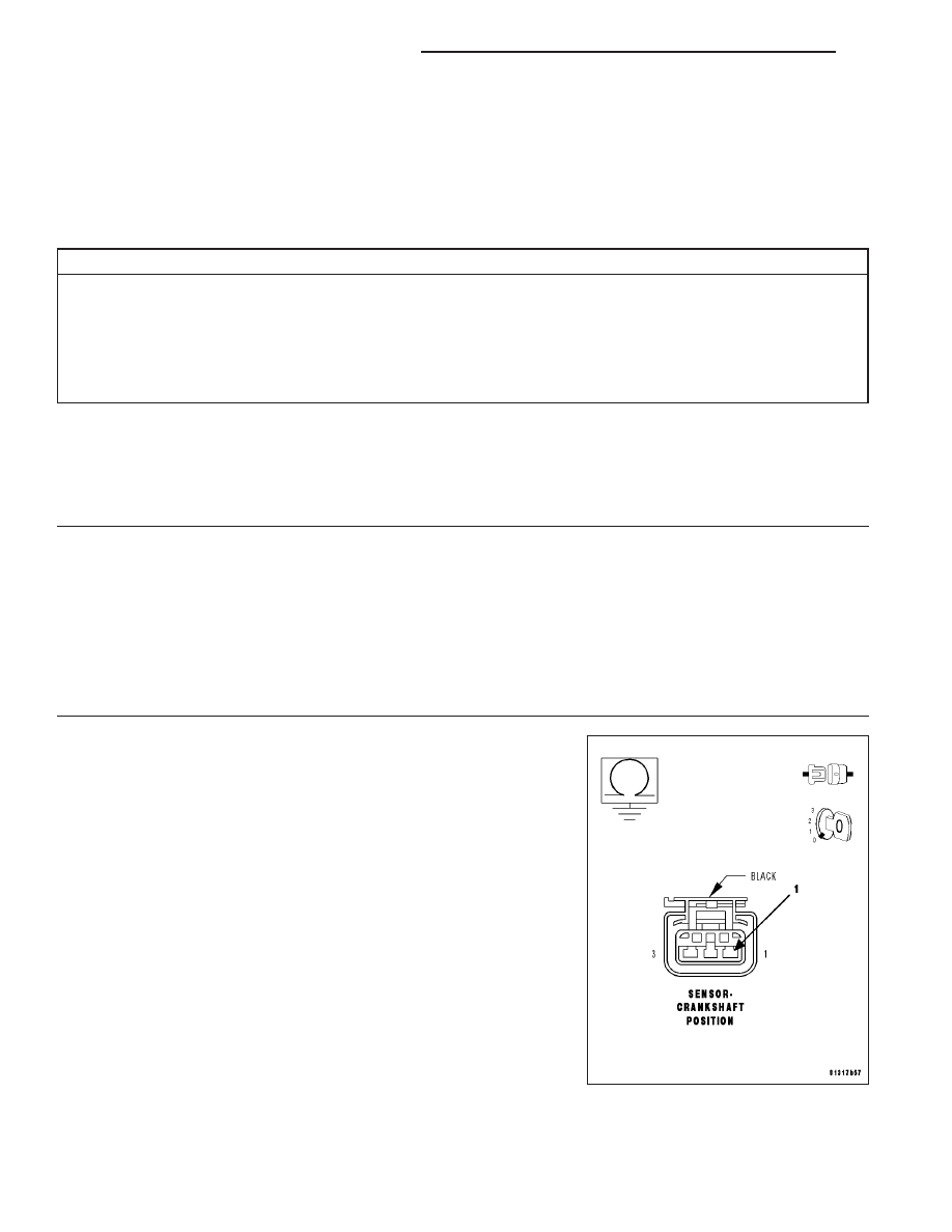
Measure the resistance between ground and the (F855) Primary 5-volt
Supply circuit in the CKP Sensor harness connector.

Is the resistance below 100 ohms?

Yes

>> Repair the short to ground in the (F855) Primary 5-volt

Supply circuit.

Perform the POWERTRAIN VERIFICATION TEST. (Refer
to 9 - ENGINE - STANDARD PROCEDURE)

No

>> Go To 3

9 - 688

ENGINE ELECTRICAL DIAGNOSTICS

LX

3.

SENSOR SHORTED TO GROUND

Connect the PCM harness connectors and all the previously discon-
nected Sensor except for the CKP Sensor harness connector.

Ignition on, engine not running.

Measure the voltage on the (F855) Primary 5-volt Supply circuit at the
Throttle Body harness connector.

CAUTION: You must Turn the Ignition Off when disconnecting any
of the Sensor harness connectors and Turn the Ignition On to
check the voltage readings.
While monitoring the voltage, disconnect each Sensor harness connec-
tor that shares the (F855) Primary 5-volt Supply circuit, one at a time.

Does the voltage increase above 4.5 volts when disconnecting
any of the Sensor harness connectors?

Yes

>> Replace the Sensor that causes the (F855) Primary 5-volt

Supply circuit voltage to increase when disconnected.

Perform the POWERTRAIN VERIFICATION TEST. (Refer
to 9 - ENGINE - STANDARD PROCEDURE)

No

>> Go To 4

4.

5-VOLT SENSOR

Turn the ignition off.

Connect all the previously disconnected Sensors except for the CKP
Sensor harness connector.

Ignition on, engine not running.

Measure the voltage on the (F855) Primary 5-volt Supply circuit at the
CKP Sensor harness connector.

Is the voltage between 4.8 and 5.2 volts?

Yes

>> Replace the Crank Position Sensor.

Perform the POWERTRAIN VERIFICATION TEST. (Refer
to 9 - ENGINE - STANDARD PROCEDURE)

No

>> Go To 5

LX

ENGINE ELECTRICAL DIAGNOSTICS

9 - 689

5.

(F855) PRIMARY 5-VOLT SUPPLY SHORTED TO BATTERY VOLTAGE

Turn the ignition off.

Disconnect the PCM harness connectors.

Disconnect all the Sensors that share the (F855) Primary 5-volt Supply
circuit.

Ignition on, engine not running.

Measure the voltage on the (F855) Primary 5-volt Supply circuit in the
CKP Sensor harness connector.

Is the voltage present?

Yes

>> Repair the short to battery voltage in the (F855) Primary

5-volt Supply circuit.

Perform the POWERTRAIN VERIFICATION TEST. (Refer
to 9 - ENGINE - STANDARD PROCEDURE)

No

>> Go To 6

6.

(F855) PRIMARY 5-VOLT SUPPLY CIRCUIT OPEN

Turn the ignition off.

Reconnect all the sensors that were disconnected in the previous step
except for the CKP Sensor harness connector.

CAUTION: Do not probe the PCM harness connectors. Probing the
PCM harness connectors will damage the PCM terminals resulting
in poor terminal to pin connection. Install Miller Special Tool #8815
to perform diagnosis.
Measure the resistance in the (F855) Primary 5-volt Supply circuit from
the Sensor harness connector to the appropriate terminal of special tool
#8815.

It may be necessary to perform this test from every sensor that uses
the (F855) Primary 5-volt Supply circuit.

Is the resistance below 5.0 ohms?

Yes

>> Go To 7

No

>> Repair the open in the (F855) Primary 5-volt Supply circuit.

Perform the POWERTRAIN VERIFICATION TEST. (Refer
to 9 - ENGINE - STANDARD PROCEDURE)

7.

PCM

NOTE: Before continuing, check the PCM harness connector terminals for corrosion, damage, or terminal
push out. Repair as necessary.
Using the schematics as a guide, inspect the wire harness and connectors. Pay particular attention to all Power and
Ground circuits.

Were there any problems found?

Yes

>> Repair as necessary.

Perform the POWERTRAIN VERIFICATION TEST. (Refer to 9 - ENGINE - STANDARD PROCEDURE)

No

>> Replace and program the Powertrain Control Module per Service Information.

Perform the POWERTRAIN VERIFICATION TEST. (Refer to 9 - ENGINE - STANDARD PROCEDURE)

9 - 690

ENGINE ELECTRICAL DIAGNOSTICS

LX

P1628-SENSOR REFERENCE VOLTAGE 2 CIRCUIT ERRATIC

For a complete wiring diagram Refer to Section 8W.

When Monitored:
Ignition on.

Set Condition:
When the PCM recognizes the Auxiliary 5-volt Supply circuit voltage is varying too much to quickly. One Trip
Fault. ETC light is flashing.

Possible Causes

(F856) AUXILIARY 5-VOLT SUPPLY SHORTED TO GROUND

(F856) AUXILIARY 5-VOLT SUPPLY SHORTED TO BATTERY VOLTAGE

(F856) AUXILIARY 5-VOLT SUPPLY CIRCUIT OPEN

5-VOLT SENSOR

PCM

Always perform the Pre-Diagnostic Troubleshooting procedure before proceeding. (Refer to 9 - ENGINE -
DIAGNOSIS AND TESTING).

Diagnostic Test

1.

ACTIVE DTC

Ignition on, engine not running.

With a scan tool, read DTCs.

Is the DTC active at this time?

Yes

>> Go To 2

No

>> Refer to the INTERMITTENT CONDITION Diagnostic Procedure.

Perform the POWERTRAIN VERIFICATION TEST. (Refer to 9 - ENGINE - STANDARD PROCEDURE)

2.

(F856) AUXILIARY 5-VOLT SUPPLY SHORTED TO GROUND

Turn the ignition off.

Disconnect the PCM harness connectors.

Disconnect all the Sensors that share the (F856) Auxiliary 5-volt Supply
circuit.

NOTE: This code can be caused by the improper installation of
after market accessories that may be causing excessive noise on
the (F856) 5-volt Supply circuit.
Measure the resistance between ground and the (F856) Auxiliary 5-volt
Supply circuit at the CMP Sensor harness connector.

Is the resistance below 100 ohms?

Yes

>> Repair the short to ground in the (F856) Auxiliary 5-volt

Supply circuit.

Perform the POWERTRAIN VERIFICATION TEST. (Refer to
9 - ENGINE - STANDARD PROCEDURE)

No

>> Go To 3

LX

ENGINE ELECTRICAL DIAGNOSTICS

9 - 691


Content   ..  1164  1165  1166  1167   ..