Chrysler 300/300 Touring/300C, Dodge Magnum. Manual - part 1154


  Index      Chrysler     Chrysler 300/300 Touring/300C, Dodge Magnum - service repair manual


Search            


Content   ..  1152  1153  1154  1155   ..


Chrysler 300/300 Touring/300C, Dodge Magnum. Manual - part 1154


4.

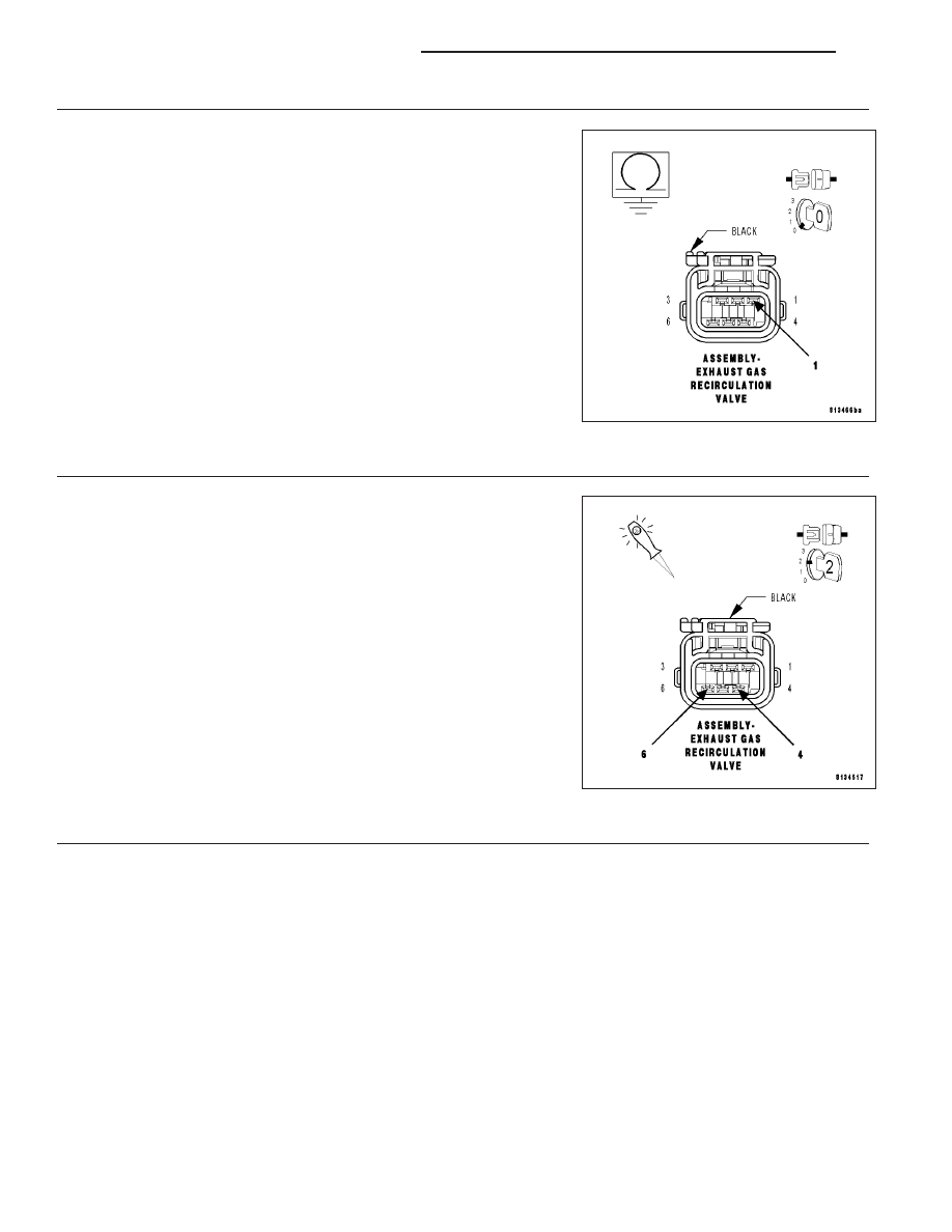
(K34) EGR SENSOR SIGNAL CIRCUIT SHORTED TO GROUND

Measure the resistance between ground and the (K34) EGR Sensor
Signal circuit in the EGR Solenoid harness connector.

Is the resistance below 5.0 ohms?

Yes

>> Repair the short to ground in the (K34) EGR Sensor Signal

circuit.

Perform the POWERTRAIN VERIFICATION TEST. (Refer
to 9 - ENGINE - STANDARD PROCEDURE)

No

>> Go To 5

5.

EGR SOLENOID ASSEMBLY

Reconnect the PCM harness connector.

Ignition on, engine not running.

Using a 12-volt test light, jumper cross the (K35) EGR Solenoid Control
circuit and the (Z904) Ground circuit in the EGR Solenoid harness con-
nector.

With the scan tool, actuate the EGR Solenoid. Allowing it to actuate for
at least 15 seconds.

Does the test light illuminate brightly and flash on and off?

Yes

>> Replace the EGR Solenoid Assembly per Service Informa-

tion.

Perform the POWERTRAIN VERIFICATION TEST. (Refer
to 9 - ENGINE - STANDARD PROCEDURE)

No

>> Go To 6

6.

PCM

NOTE: Before continuing, check the PCM harness connector terminals for corrosion, damage, or terminal
push out. Repair as necessary.
Using the schematics as a guide, inspect the wire harness and connectors. Pay particular attention to all Power and
Ground circuits.

Were there any problems found?

Yes

>> Repair as necessary.

Perform the POWERTRAIN VERIFICATION TEST. (Refer to 9 - ENGINE - STANDARD PROCEDURE)

No

>> Replace and program the Powertrain Control Module per Service Information.

Perform the POWERTRAIN VERIFICATION TEST. (Refer to 9 - ENGINE - STANDARD PROCEDURE)

9 - 640

ENGINE ELECTRICAL DIAGNOSTICS

LX

P1411–CYLINDER 1 REACTIVATION CONTROL PERFORMANCE

LX

ENGINE ELECTRICAL DIAGNOSTICS

9 - 641

Theory of Operation

When all criteria has been met, power is supplied to each MDS Solenoid when the engine is making a transition
from 8 cylinder mode to 4 cylinder mode. By actuating the solenoid, oil pressure is raised to the pair of lifters that
coincide with each particular solenoid. The oil pressure pushes in the locking pins that allows the lifter to collapse,
decoupling the valves and camshaft.

When Monitored:
Transition from 4 to 8 cylinder mode.

Set Condition:
The MDS fails to disengage for cylinder 1.

Possible Causes

(K451) MDS SOLENOID NO.1 CONTROL SHORT TO VOLTAGE

OIL PASSAGES RESTRICTED

LIFTER

MDS SOLENOID NO.1

PCM

Always perform the Pre-Diagnostic Troubleshooting procedure before proceeding. (Refer to 9 - ENGINE -
DIAGNOSIS AND TESTING).

Diagnostic Test

1.

ACTIVE DTC

Ignition on, engine not running.

With a scan tool, read DTCs.

Is the DTC active at this time?

Yes

>> Go To 2

No

>> Refer to the INTERMITTENT CONDITION Diagnostic Procedure.

Perform the POWERTRAIN VERIFICATION TEST. (Refer to 9 - ENGINE - STANDARD PROCEDURE)

2.

(K451) MDS SOLENOID NO.1 CONTROL CIRCUIT SHORTED TO VOLTAGE

Turn the ignition off.

Disconnect the PCM harness connector.

Disconnect the C101 harness connector.

CAUTION: Do not probe the PCM harness connectors. Probing the PCM harness connectors will damage
the PCM terminals resulting in poor terminal to pin connection. Install Miller Special Tool #8815 to perform
diagnosis.
Turn the ignition on.

Measure the voltage on (K451) MDS Solenoid No.1 Control circuit in the appropriate terminal of special tool #8815.

Is voltage present?

Yes

>> Repair the short to voltage in the (K451) MDS Solenoid No.1 Control circuit.

Perform the POWERTRAIN VERIFICATION TEST. (Refer to 9 - ENGINE - STANDARD PROCEDURE)

No

>> Go To 3

9 - 642

ENGINE ELECTRICAL DIAGNOSTICS

LX

3.

MDS SOLENOID RESISTANCE

Turn the ignition off.

Measure the resistance between the (Z904) Ground Circuit and the (K451) MDS Solenoid No.1 Control Circuit in the
appropriate terminals of special tool #8815.

NOTE: It is important to follow the below temp/resistance values to ensure an accurate reading.

MDS SOLENOID RESISTANCE

TEMPERATURE VALUE ± 20° F

RESISTANCE (OHMS) ± .25 ohms

0° F

8.8 ohms

32° F

9.5 ohms

68° F

10.3 ohms

100° F

11 ohms

150° F

12.2 ohms

200° F

13.4 ohms

250° F

14.4 ohms

300° F

15.6 ohms

Is the resistance within an acceptable range?

Yes

>> Go To 4

No

>> Visually and Physically inspect the wiring harness between the C101 connector and the MDS Solenoid

connector. Repair as necessary. If OK, replace the MDS Solenoid in accordance with the Service Infor-
mation.

4.

PCM CONTROL

Turn the ignition off.

Reconnect the PCM harness connector.

Disconnect the C100 harness connector.

Ignition on, engine not running.

Using a 12-volt test light connected to the (Z904) Ground circuit, probe the (K451) MDS Solenoid No.1 Control
circuit in the C100 harness connector.

With a scan tool, actuate the MDS Solenoid.

Does the 12-volt test light flash on and off?

Yes

>> Go To 5

No

>> Replace and program the Powertrain Control Module in accordance with the Service Information.Per-

form the POWERTRAIN VERIFICATION TEST. (Refer to 9 - ENGINE - STANDARD PROCEDURE)

LX

ENGINE ELECTRICAL DIAGNOSTICS

9 - 643


Content   ..  1152  1153  1154  1155   ..