Content .. 1146 1147 1148 1149 ..
Chrysler 300/300 Touring/300C, Dodge Magnum. Manual - part 1148
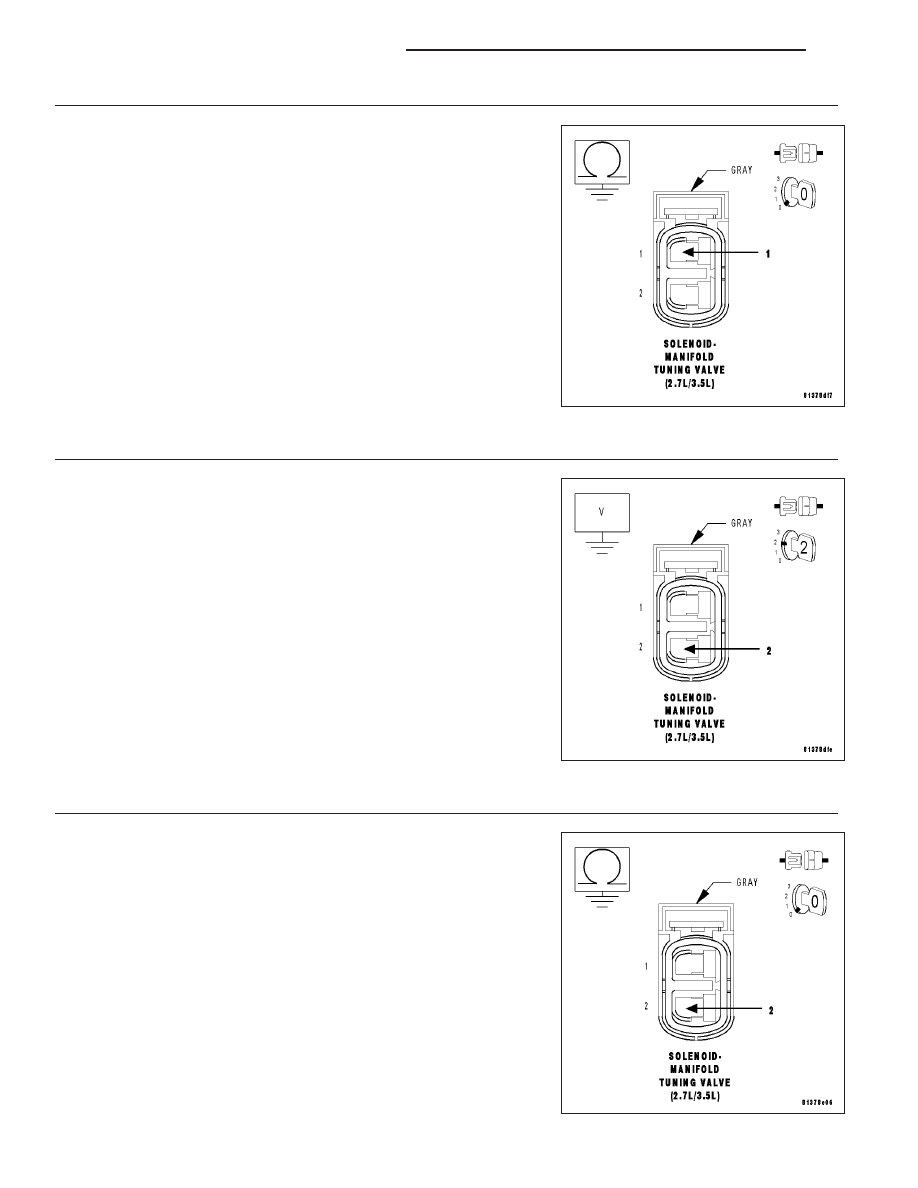
3.
MTV SOLENOID (Z904) GROUND CIRCUIT OPEN
Measure the resistance between the Ground circuit in the MTV Sole-
noid harness connector and ground.
Is the resistance below 5.0 ohms?
Yes
>> Go To 4
No
>> Repair the open in the MTV Solenoid Ground circuit.
Perform the POWERTRAIN VERIFICATION TEST. (Refer
to 9 - ENGINE - STANDARD PROCEDURE)
4.
(K136) MTV CONTROL CIRCUIT SHORT TO BATTERY VOLTAGE
Turn the ignition off
Disconnect the PCM harness connectors.
Turn the ignition on.
Measure the voltage of the (K136) MTV Control circuit in the MTV Sole-
noid harness connector.
Does the voltage indicate voltage present?
Yes
>> Repair the short to voltage in the (K136) MTV Control cir-
cuit.
Perform the POWERTRAIN VERIFICATION TEST. (Refer
to 9 - ENGINE - STANDARD PROCEDURE)
No
>> Go To 5
5.
(K136) MTV CONTROL CIRCUIT SHORT TO GROUND
Turn the ignition off.
Measure the resistance between the (K136) MTV Control circuit in the
MTV Solenoid harness connector and ground.
Is the resistance below 5.0 ohms?
Yes
>> Repair the short to ground in the (K136) MTV Control cir-
cuit.
Perform the POWERTRAIN VERIFICATION TEST. (Refer
to 9 - ENGINE - STANDARD PROCEDURE)
No
>> Go To 6
9 - 616
ENGINE ELECTRICAL DIAGNOSTICS
LX