Content .. 1141 1142 1143 1144 ..
Chrysler 300/300 Touring/300C, Dodge Magnum. Manual - part 1143
3.
(F20) FUSED IGNITION SWITCH OUTPUT CIRCUIT
Ignition on, engine not running.
Using a 12-volt test light connected to ground, probe the (F20) Fused
Ignition Switch Output circuit.
Does the test light illuminate brightly?
Yes
>> Go To 5
No
>> Repair the open or short to ground in the (F20) Fused Igni-
tion Switch Output circuit. Inspect the related fuse and
repair as necessary.
Perform the POWERTRAIN VERIFICATION TEST. (Refer
to 9 - ENGINE - STANDARD PROCEDURE)
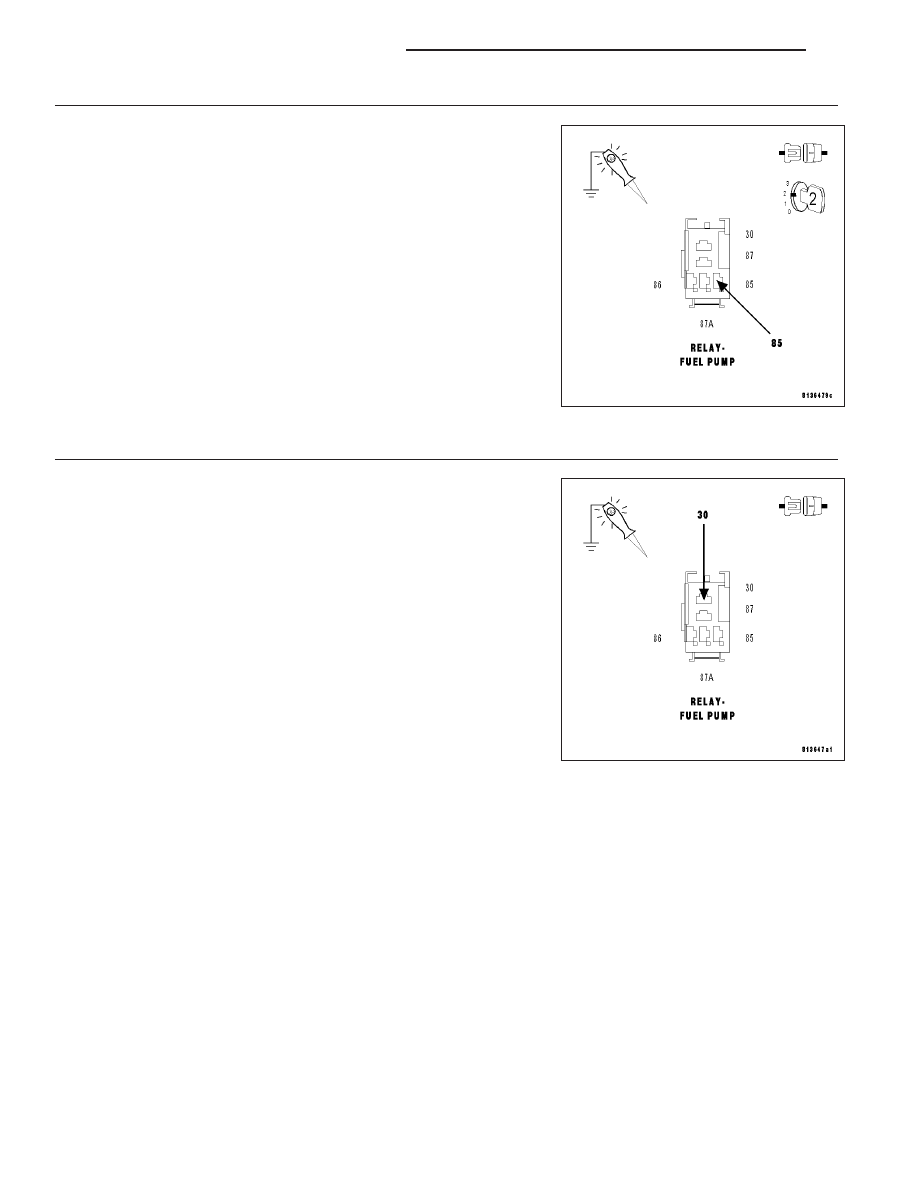
4.
(A109) FUSED B+ CIRCUIT
Ignition on, engine not running.
Using a 12-volt test light connected to ground, probe the (A109) Fused
B+ circuit.
Does the test light illuminate brightly?
Yes
>> Go To 5
No
>> Repair the open or short to ground in the (A109) Fused B+
circuit. Inspect the related fuse and repair as necessary.
Perform the POWERTRAIN VERIFICATION TEST. (Refer
to 9 - ENGINE - STANDARD PROCEDURE)
9 - 596
ENGINE ELECTRICAL DIAGNOSTICS
LX