Content .. 1087 1088 1089 1090 ..
Chrysler 300/300 Touring/300C, Dodge Magnum. Manual - part 1089
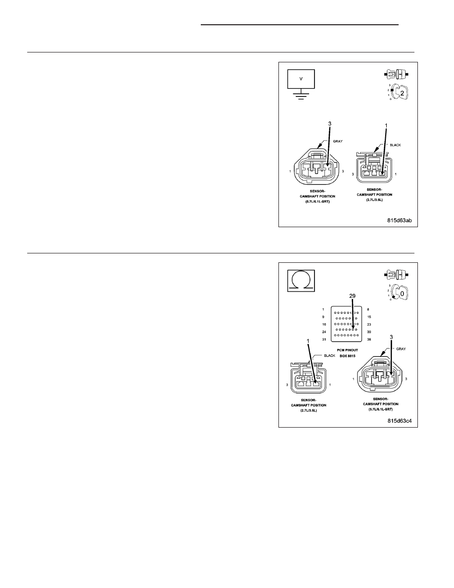
10.
(F856) 5-VOLT SUPPLY CIRCUIT SHORTED TO BATTERY VOLTAGE
Turn the ignition off.
Disconnect the PCM harness connectors.
Ignition on, engine not running.
Measure the voltage on the (F856) 5-volt Supply circuit in the CMP
Sensor harness connector.
Is the voltage above 0 volts?
Yes
>> Repair the short to battery voltage in the (F856) 5-volt Sup-
ply circuit.
Perform the POWERTRAIN VERIFICATION TEST. (Refer to
9 - ENGINE - STANDARD PROCEDURE)
No
>> Go To 11
11.
(F856) 5-VOLT SUPPLY CIRCUIT OPEN
Turn the ignition off.
CAUTION: Do not probe the PCM harness connectors. Probing the
PCM harness connectors will damage the PCM terminals resulting
in poor terminal to pin connection. Install Miller Special Tool #8815
to perform diagnosis.
Measure the resistance of the (F856) 5-volt Supply circuit between the
CMP Sensor harness connector to the appropriate terminal of special
tool #8815.
Is the resistance below 5.0 ohms?
Yes
>> Go To 12
No
>> Repair the open in the (F856) 5-volt Supply circuit.
Perform the POWERTRAIN VERIFICATION TEST. (Refer to
9 - ENGINE - STANDARD PROCEDURE)
9 - 380
ENGINE ELECTRICAL DIAGNOSTICS
LX