Content .. 1051 1052 1053 1054 ..
Chrysler 300/300 Touring/300C, Dodge Magnum. Manual - part 1053
•
When Monitored:
With battery voltage greater than 10 volts. Auto Shutdown Relay energized. Engine speed less than 3000 rpm.
•
Set Condition:
No inductive spike is detected after injector turn off.
Possible Causes
(K343) ASD RELAY OUTPUT 2 CIRCUIT
(K14) INJECTOR CONTROL NO.4 CIRCUIT OPEN
(K14) INJECTOR CONTROL NO.4 CIRCUIT SHORTED TO GROUND
FUEL INJECTOR
PCM
Always perform the Pre-Diagnostic Troubleshooting procedure before proceeding. (Refer to 9 - ENGINE -
DIAGNOSIS AND TESTING).
Diagnostic Test
1.
ACTIVE DTC
Ignition on, engine not running.
With a scan tool, read DTCs.
Is the DTC active at this time?
Yes
>> Go To 2
No
>> Refer to the INTERMITTENT CONDITION Diagnostic Procedure.
Perform the POWERTRAIN VERIFICATION TEST. (Refer to 9 - ENGINE - STANDARD PROCEDURE)
2.
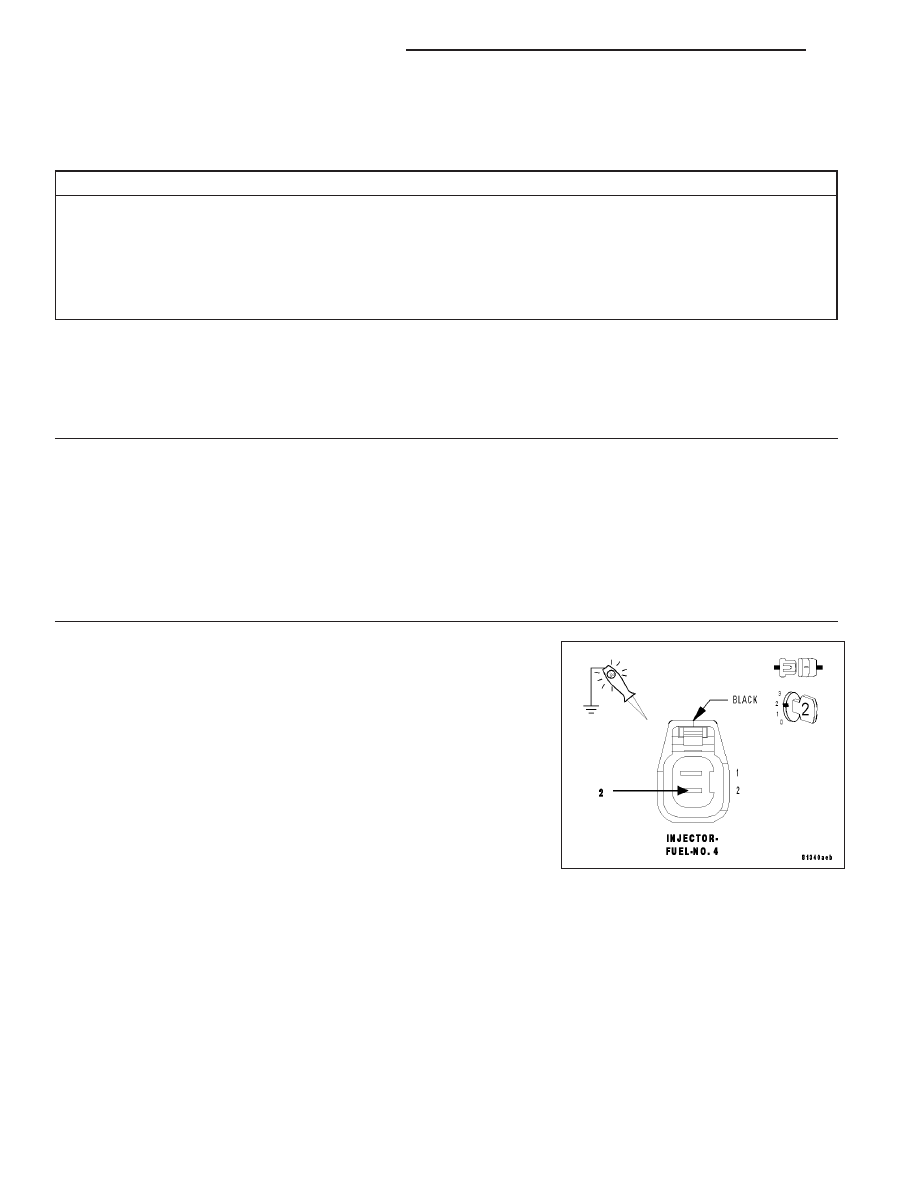
(K343) ASD RELAY OUTPUT 2 CIRCUIT
Turn the ignition off.
Disconnect the No.4 Fuel Injector harness connector.
Ignition on, engine not running.
With the scan tool, actuate the ASD Relay.
Using a 12-volt test light connected to ground, backprobe the (K343)
ASD Relay Output 2 circuit in the No.4 Fuel Injector harness connector.
Does the test light illuminate brightly?
Yes
>> Go To 3
No
>> Repair the excessive resistance or short to ground in the
(K343) ASD Relay Output 2 circuit.
Perform the POWERTRAIN VERIFICATION TEST. (Refer
to 9 - ENGINE - STANDARD PROCEDURE)
9 - 236
ENGINE ELECTRICAL DIAGNOSTICS
LX