Content .. 1021 1022 1023 1024 ..
Chrysler 300/300 Touring/300C, Dodge Magnum. Manual - part 1023
•
When Monitored:
With the ignition key on. No Cam or Crank signal within 75 ms. Engine speed less than 250 RPM.
•
Set Condition:
The PCM senses the voltage from the MAP sensor to be less than 2.2 volts but above 0.04 of a volt for 300
milliseconds. One Trip Fault. Three good trips to turn off the MIL. (ETC lamp will flash)
Possible Causes
(F856) 5-VOLT SUPPLY CIRCUIT SHORTED TO BATTERY VOLTAGE
(F856) 5-VOLT SUPPLY CIRCUIT OPEN
(F856) 5-VOLT SUPPLY CIRCUIT SHORTED TO GROUND
(K1) MAP SIGNAL CIRCUIT OPEN
(K1) MAP SIGNAL CIRCUIT SHORTED TO GROUND
(K1) MAP SIGNAL CIRCUIT SHORTED TO (K900) SENSOR GROUND
MAP SENSOR
PCM
Always perform the Pre-Diagnostic Troubleshooting procedure before proceeding. (Refer to 9 - ENGINE -
DIAGNOSIS AND TESTING).
Diagnostic Test
1.
ACTIVE DTC
Ignition on, engine not running.
With a scan tool, read DTCs.
Is the DTC active at this time.
Yes
>> Go To 2
No
>> Refer to the INTERMITTENT CONDITION Diagnostic Procedure.
Perform the POWERTRAIN VERIFICATION TEST. (Refer to 9 - ENGINE - STANDARD PROCEDURE)
2.
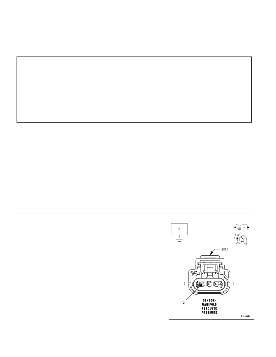
(F856) 5-VOLT SUPPLY CIRCUIT
Turn the ignition off.
Disconnect the MAP Sensor harness connector.
Ignition on, engine not running.
Measure the voltage on the (F856) 5-volt Supply circuit in the MAP
Sensor harness connector.
Is the voltage between 4.5 to 5.2 volts?
Yes
>> Go To 3
No
>> Go To 7
9 - 116
ENGINE ELECTRICAL DIAGNOSTICS
LX